The Images back
The first step was getting the hardware, wasnt that easy but i got it.
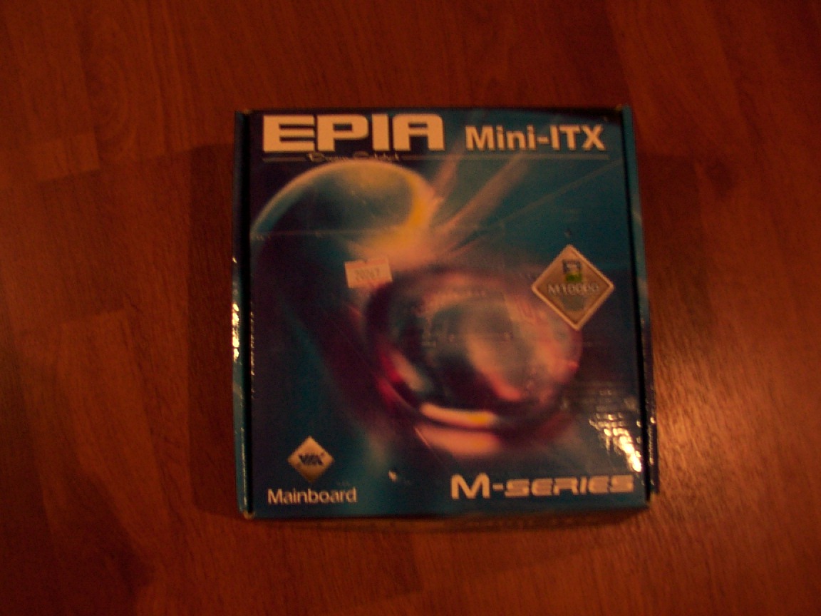
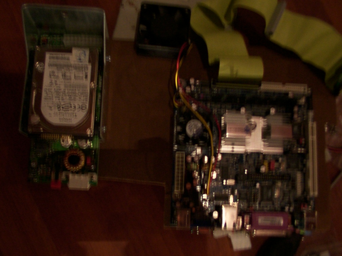
Via epia m10000 Mobo - arrived
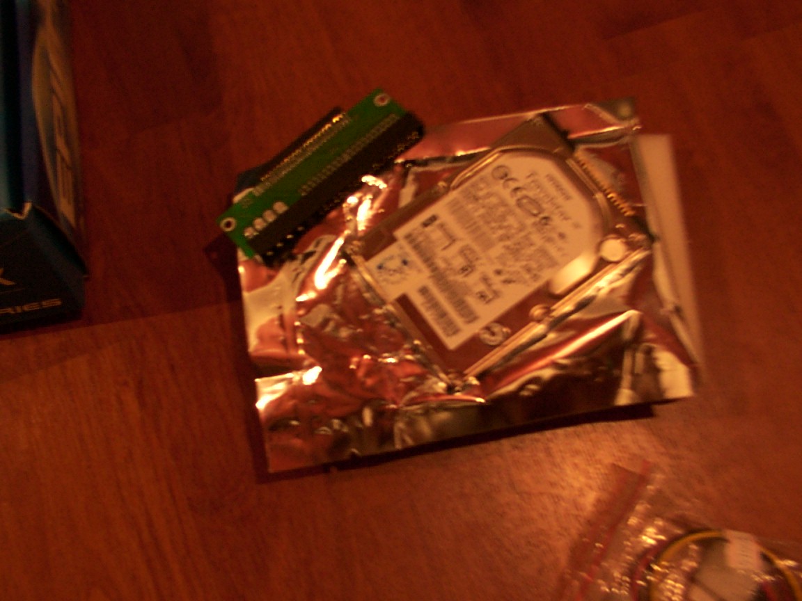
2.5" 20gb 5400 rpm hd arrived and its ide adapter too.The ide adapter is the board, the hdd is that small silver rectangle :)
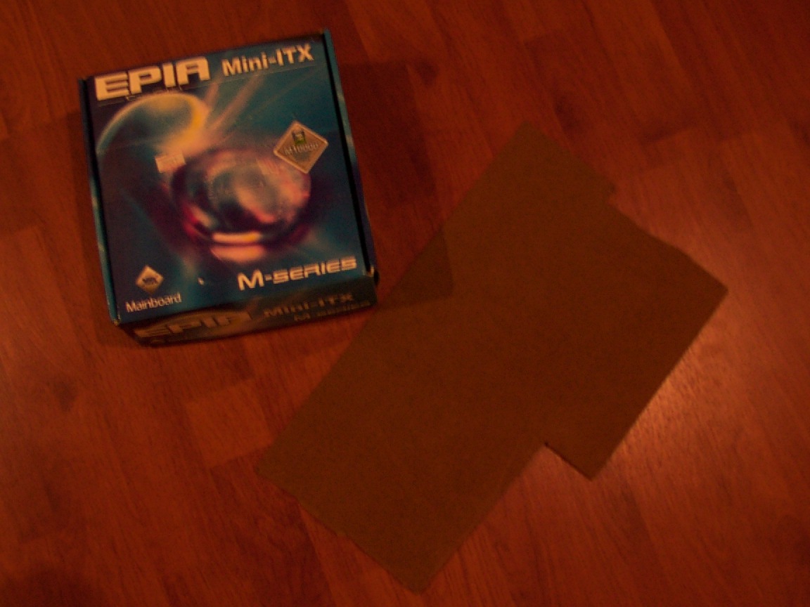
The board case and the soon to be platform for that whole carputer, that wooden frame carved in the glovebox shape.
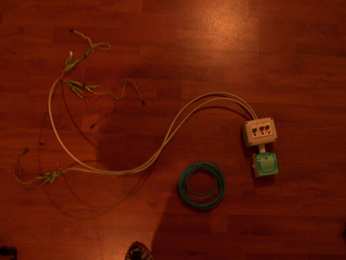
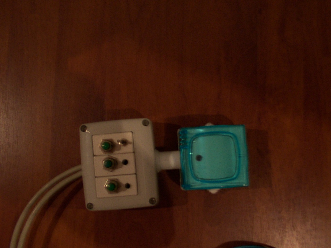
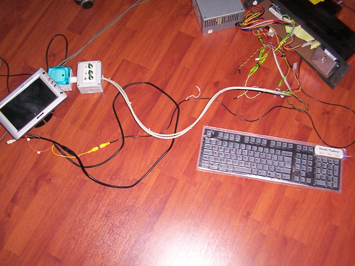
The control box(maybe a temporary one) with 2 LAN cables(RJ45 CAT5E) for the buttons to be controlled by A very slick idea if i might add :)
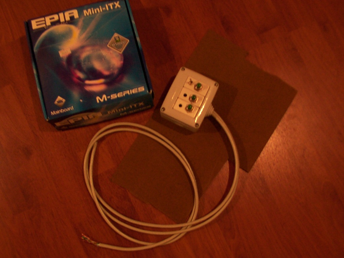
Lets see: Restart,Sleep,FFU and the on/off for the power switch. (to be more p.c. for the power cut not power switch)
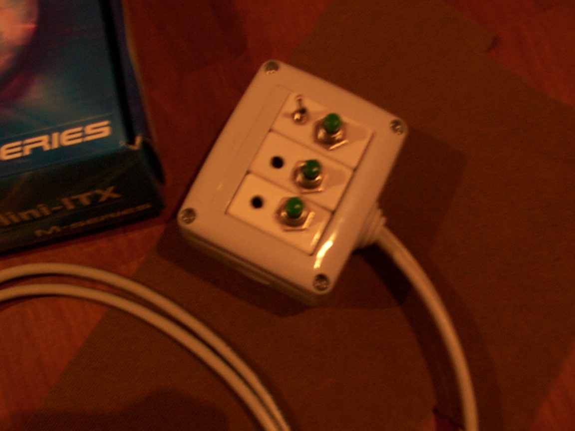
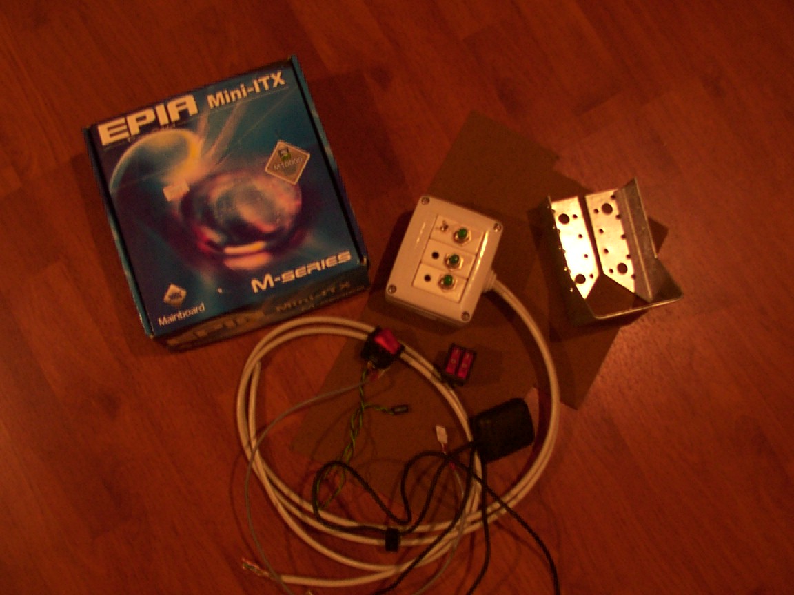
The control box (its not wired yet as you can see) the usb gps and a steel trapezoid i've found in a shop to be used hopefully by the hdd and the opus psu, like a bay.
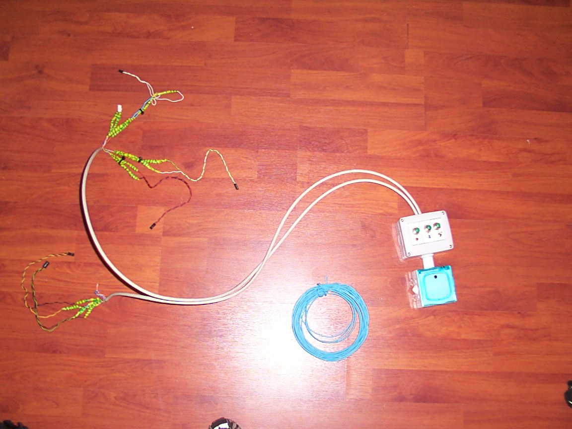
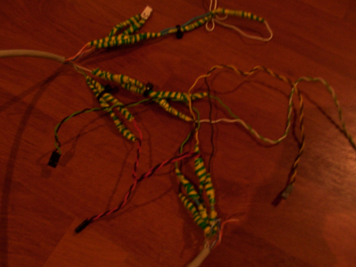
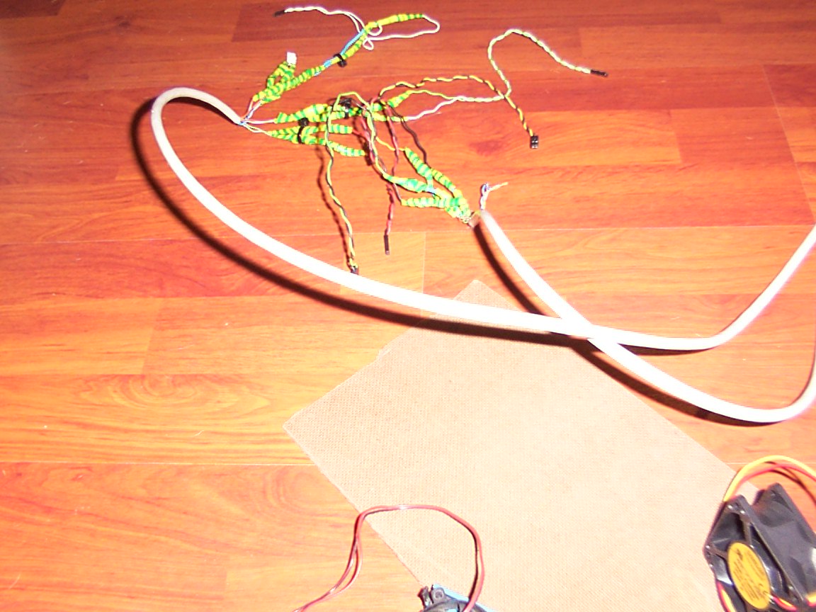
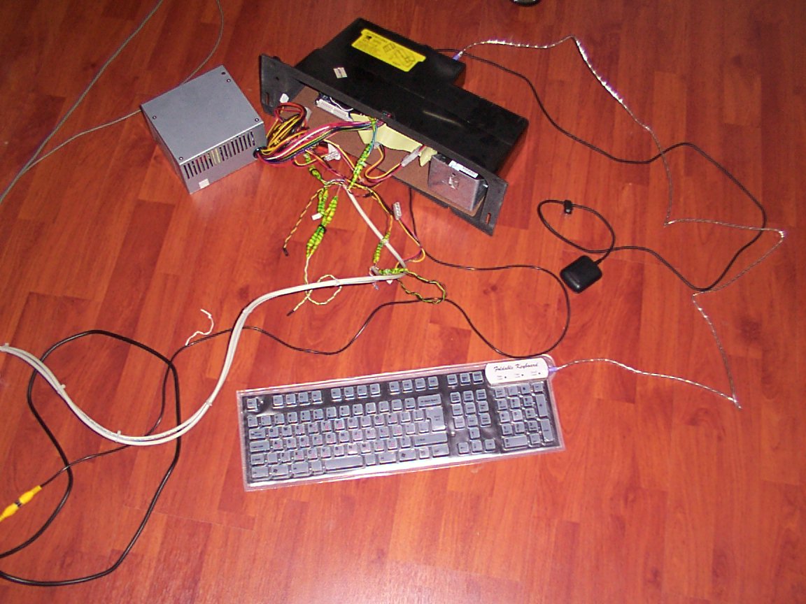
The control box finished after soldering the cables.Lemme say a few words on the process:
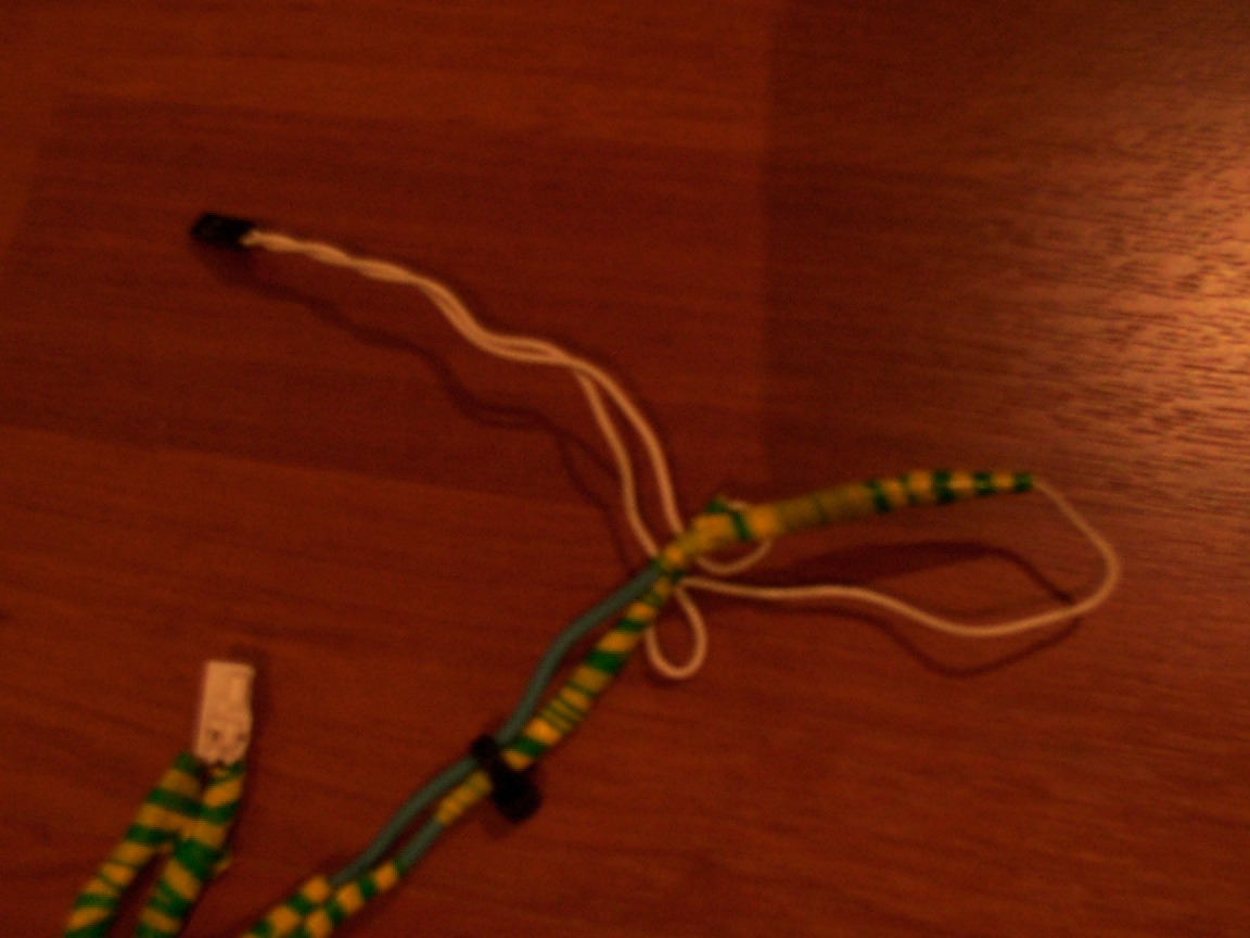
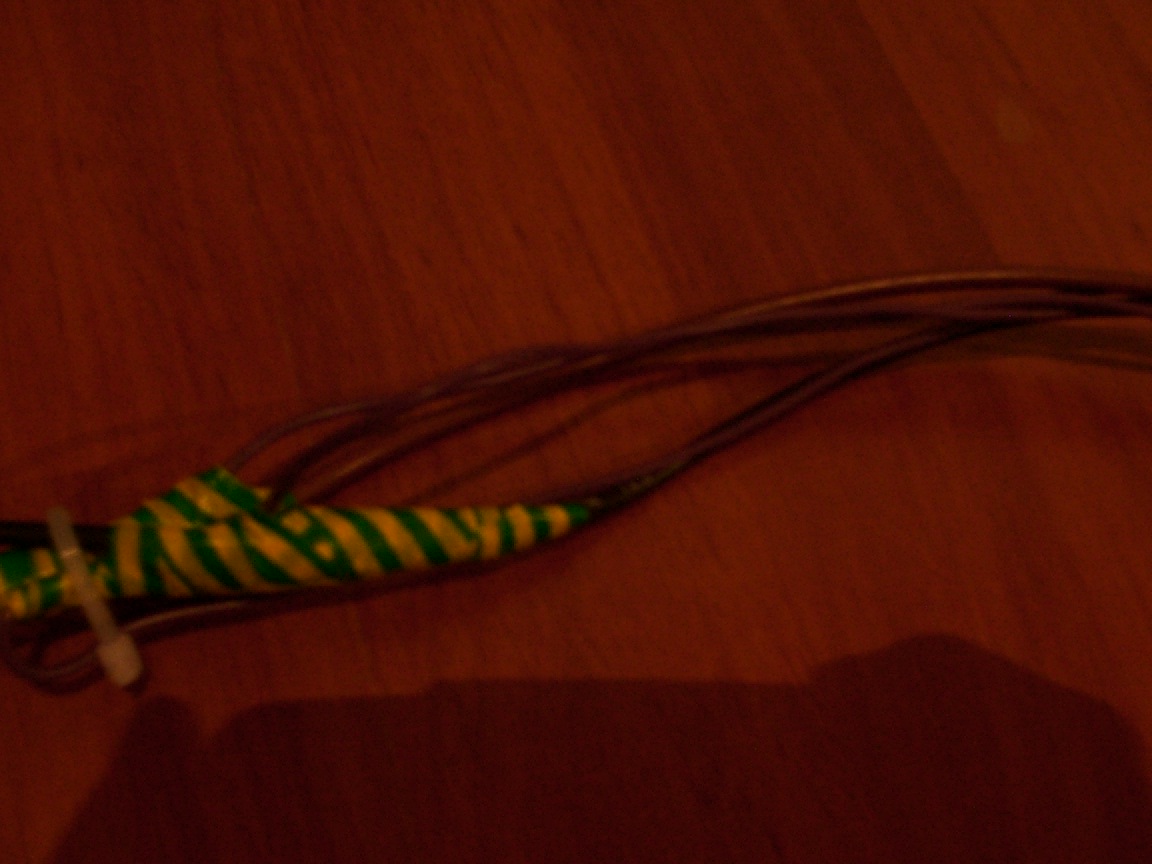
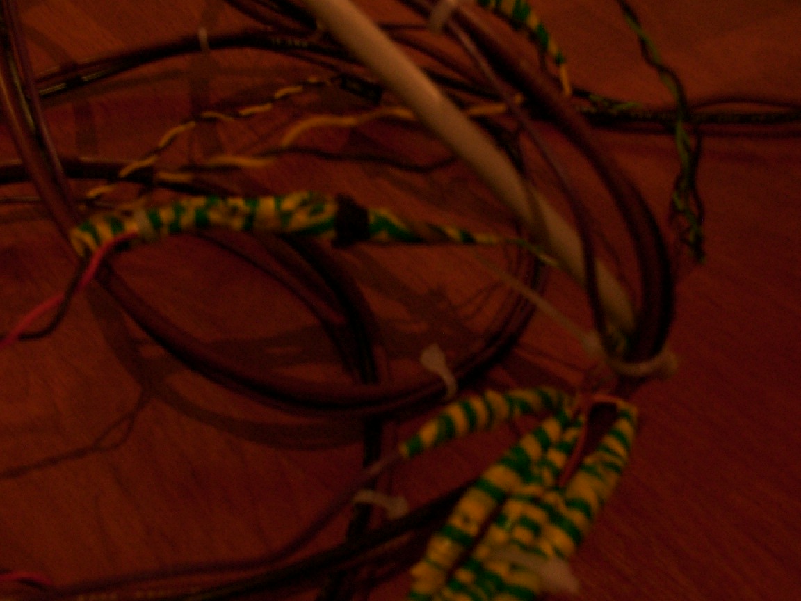
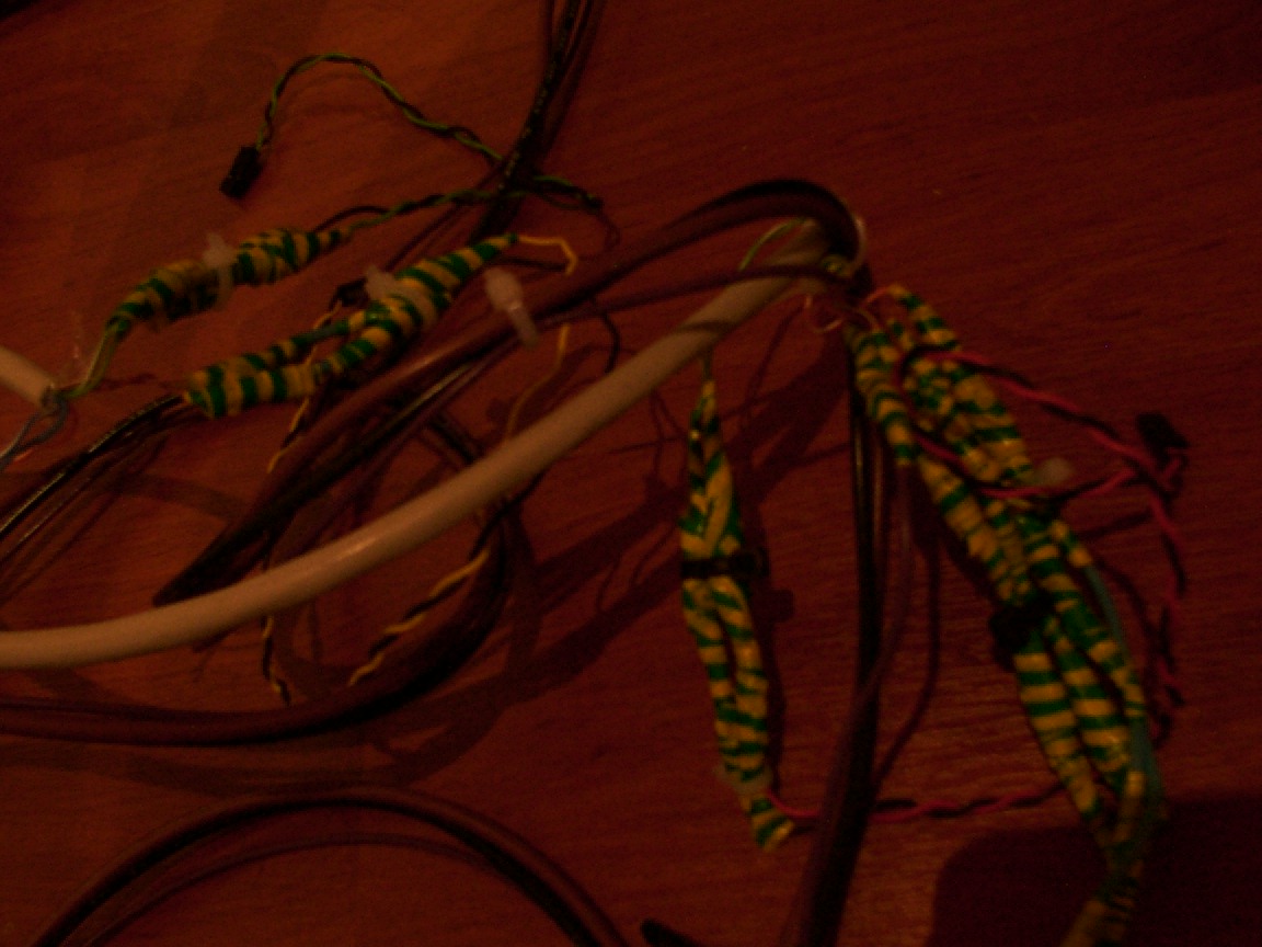
Because you need power/restart/... buttons , you have to make their connection to the MOBO.Now i've used lan cables(RJ45 CAT5E SWG24 if youd like to know) as the conductors.Two of them meaning 16 tendons , because each button takes 2 that leaves us with 8 button/8 leds you got the point.
Now if you'd solder the cables straight to the pins it wouldnt work because it wont get enough "signal" what i did was: You see the blue cable there? its a simple electricity cable, it conducts very good, it "amplifies" the signal.So i took small part of it like a 2cm piece and soldered each piece to a tendon as you can see, one side connects the wire to the pins the other to the lan cable. The blue electricity wire is under the green/yellow insulting tape.It works like a dream afterwards.
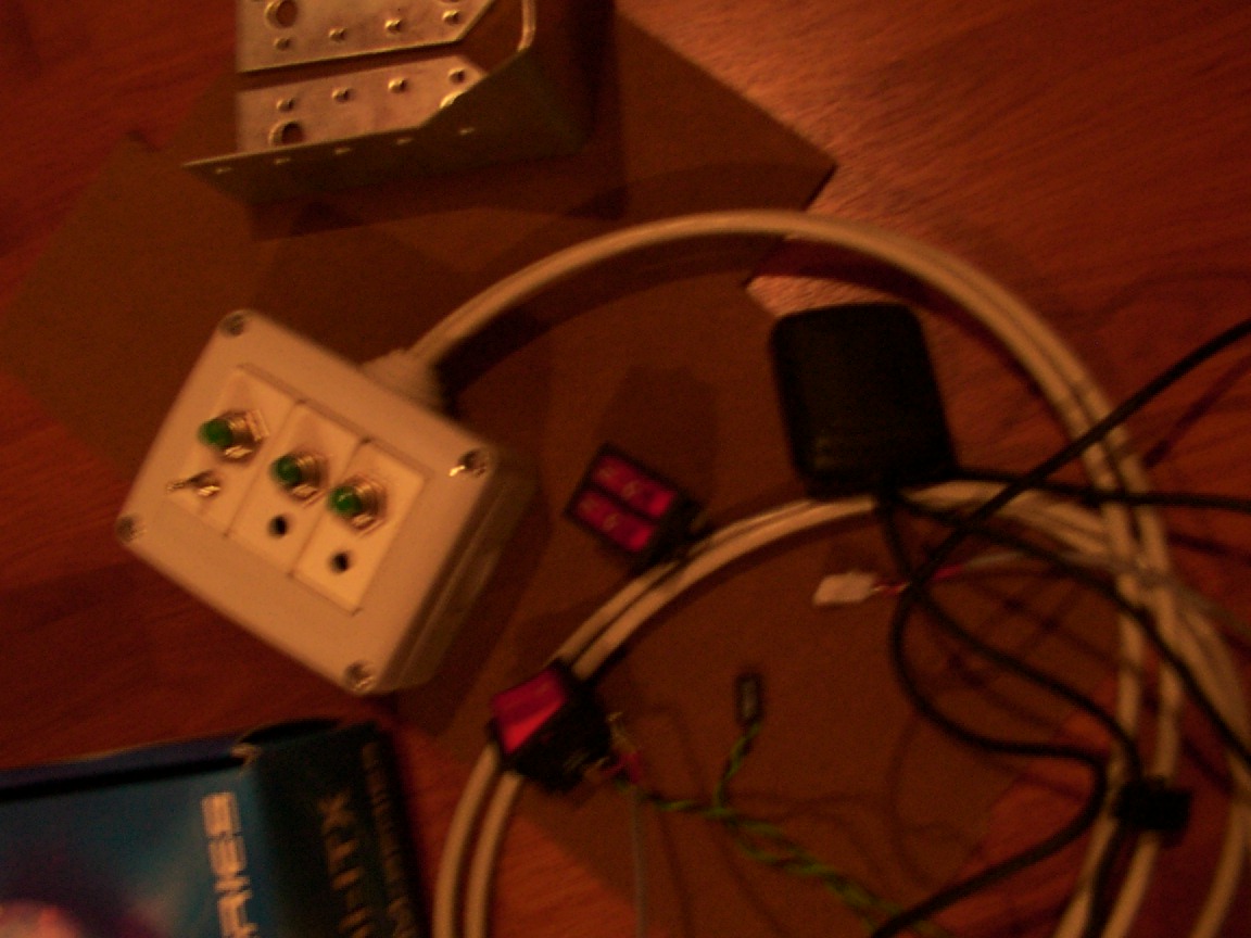
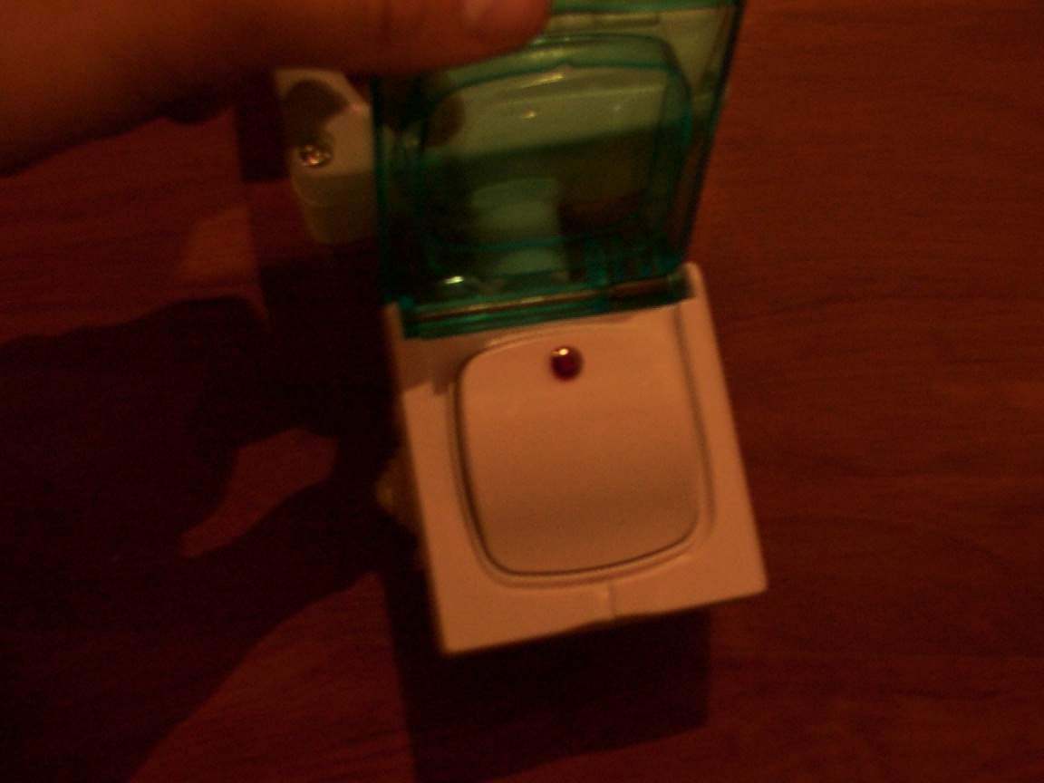
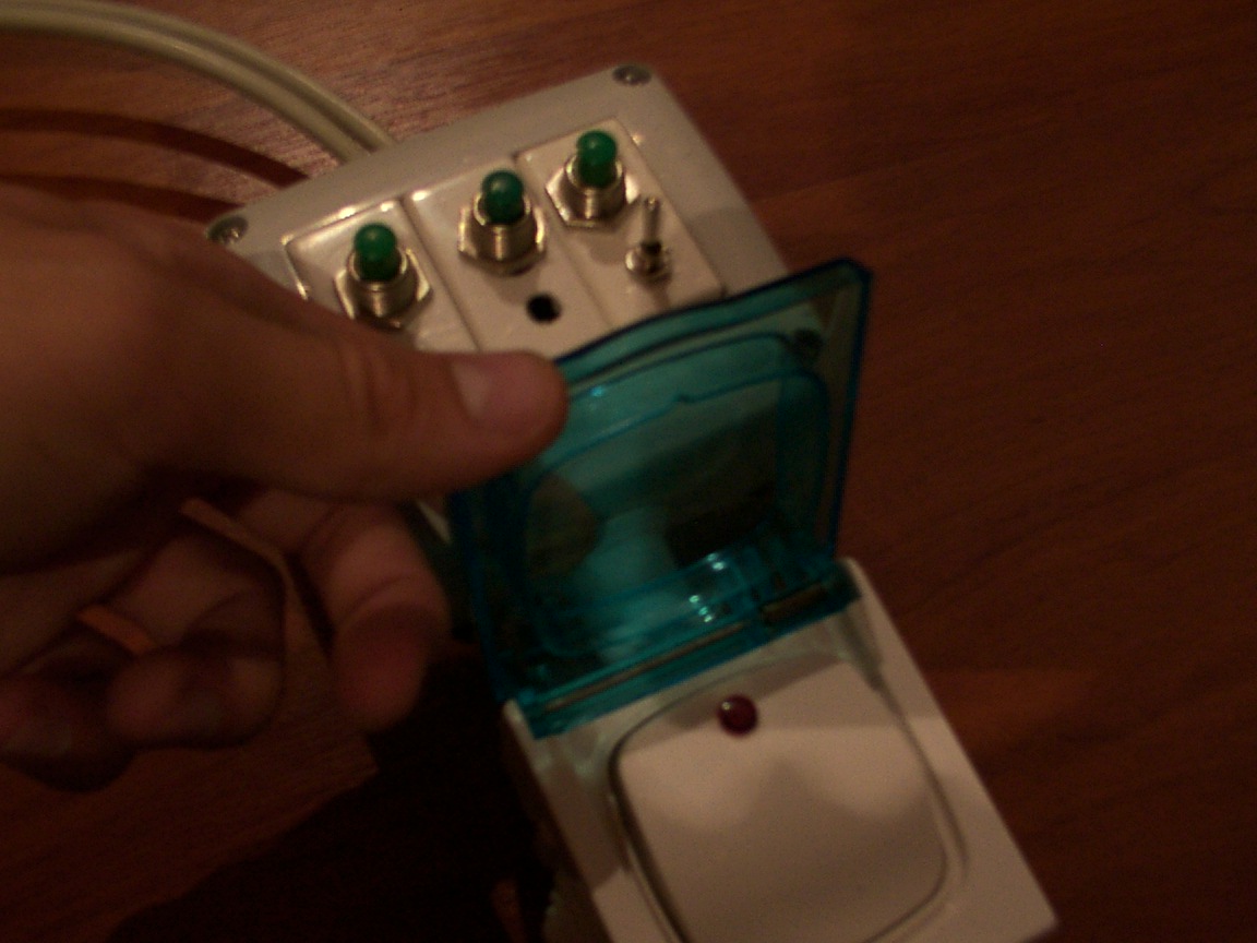
The "Improved" control box, got a big button, actually its a button with a led inside and a plastic cover its for stairwells.I've used it as the power button looks good.
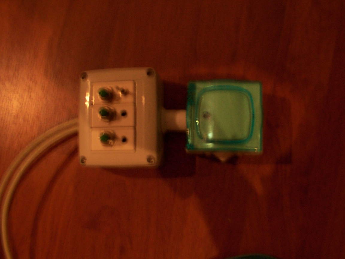

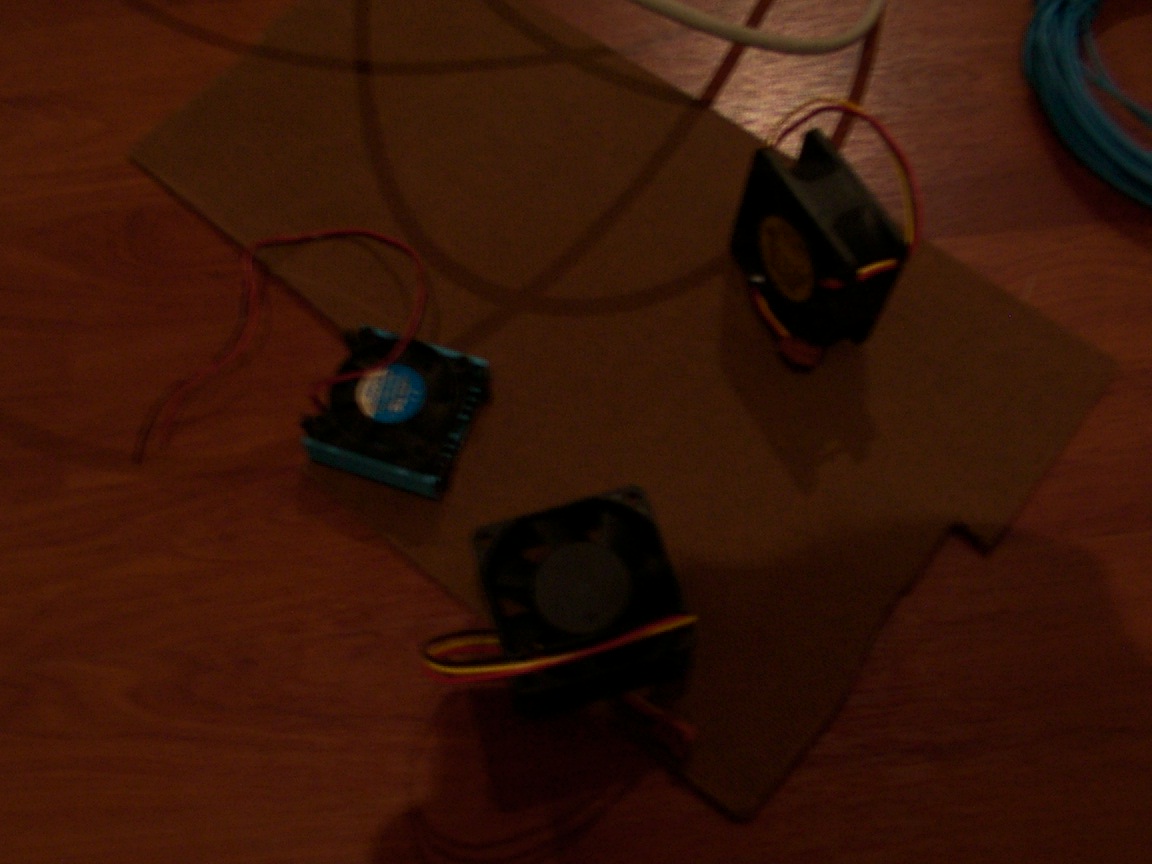
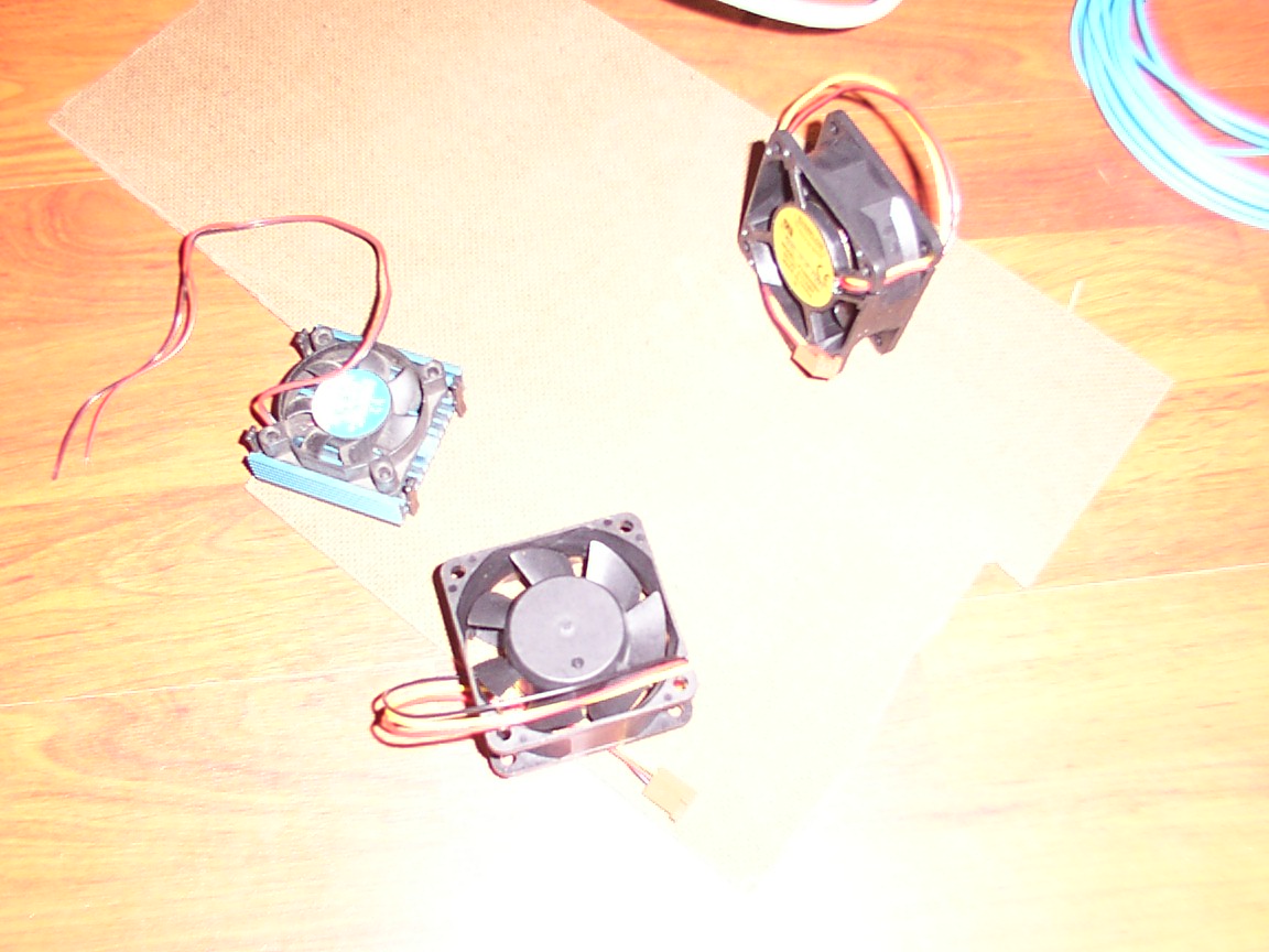
The right bottomed one is the fan to be used, a 4500 rpm fan,in summer here it could get up to 60c in a closed and hot place...like a car's glovebox.
As you can see i've mounted the hdd and the opus 90w psu on the steel bay.Even though its a notebook hdd, i've attached shock absorbers in the form of rubber bands, so that when if necessary they will protect the hdd from impact. We got lots of speed bumps here... not a good thing for a hdd. The opus is mounted right underneath it also on rubber bands. Because they elevated it a little and they enhanced the grip of the it.
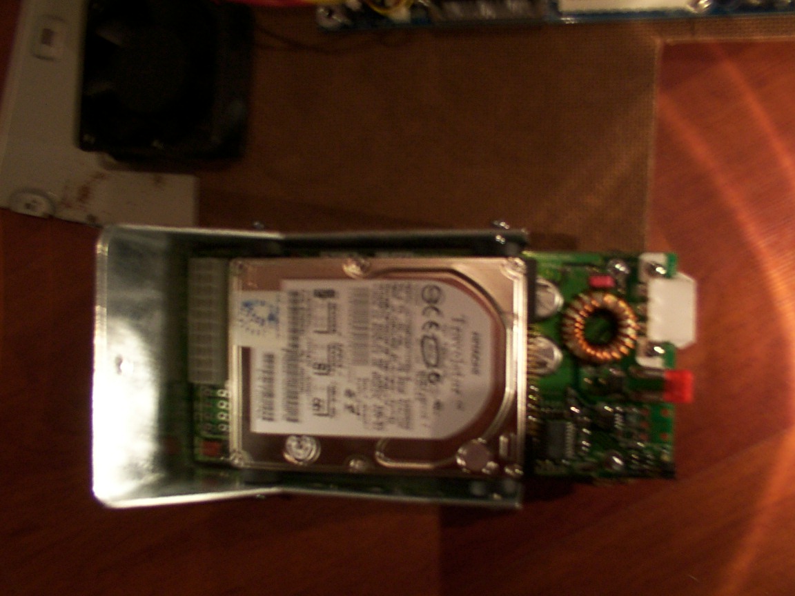

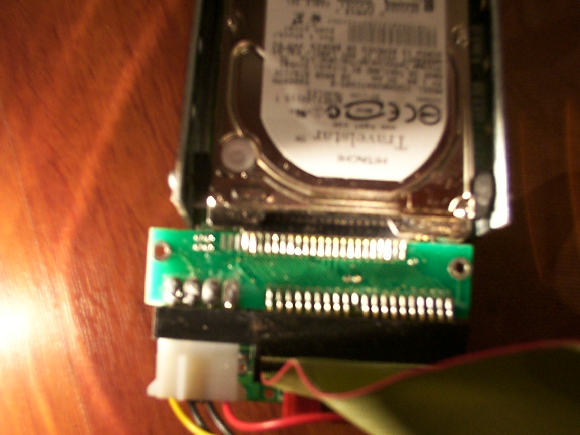
The hdd is connected to the ide (2.5" -> 3.5") adapter

Because in 2.5" ide theres no need of that much of electricity like in 3.5" several tendons of the ide are supplying the power.So in the board you can see they becomes the dc input.
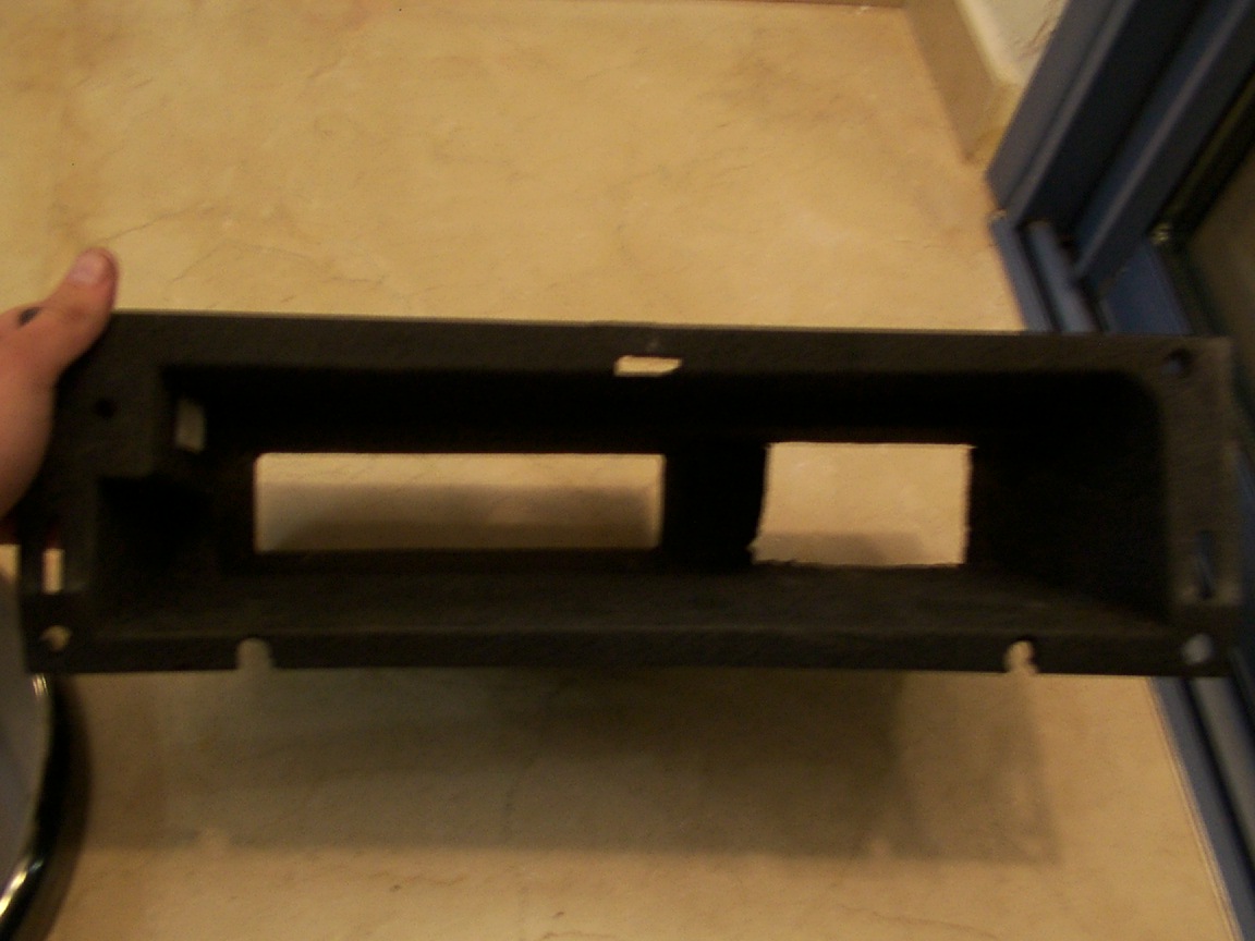
Weehee i've took the glovebox off the car, this is the new house of my carpc, say cheese!
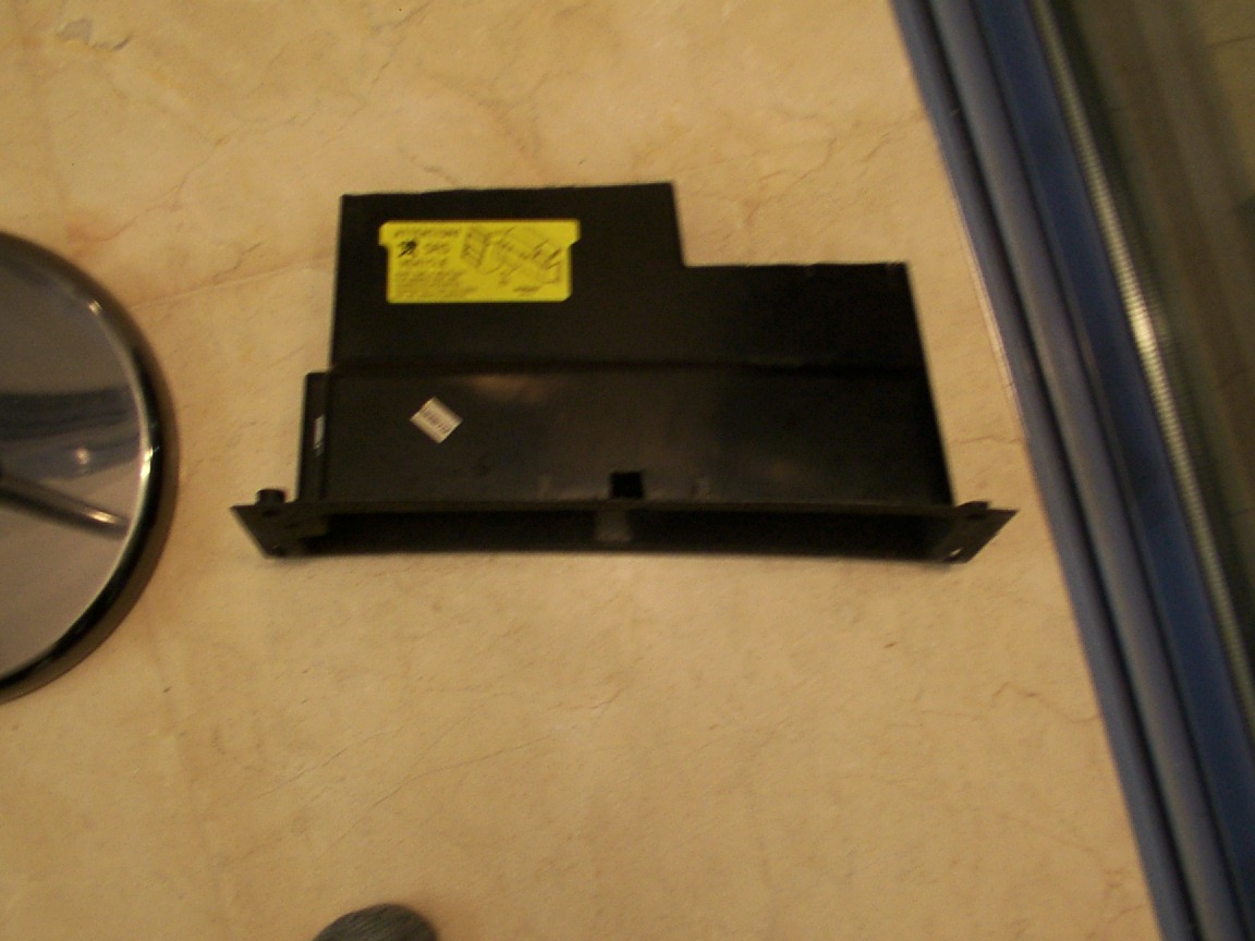
The right most open hole is for the PSU cables, the left most is for the MOBO's outs/ins
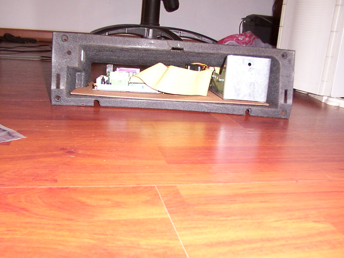
This is how it looks after i've pushed it all in, starting to look like a carpc ha :)
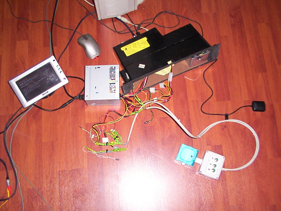
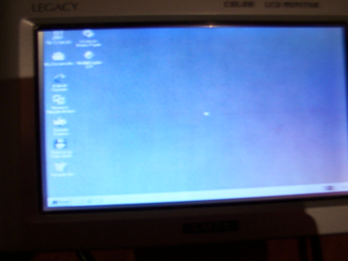
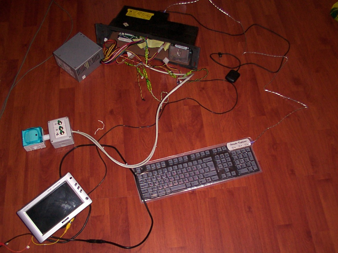
Here i've connected the monitor to the carpc before ive got my keyboard and mouse, after installing WIN98SE
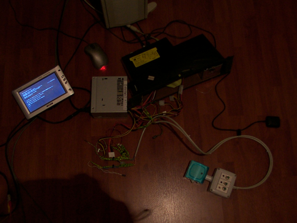
How it looks when the lights are off :)
Note that i use here a regular PSU, not the opus , i use a 300Wat heck AC->DC psu, and my monitor connected through AC.
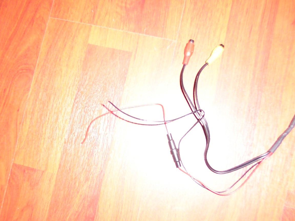
The next step was soldering the monitors's electricity cables, theres a red and black one, red-positive black-negative(GND), next i'll explain what to do.The black thing in the red cable is a fuse.
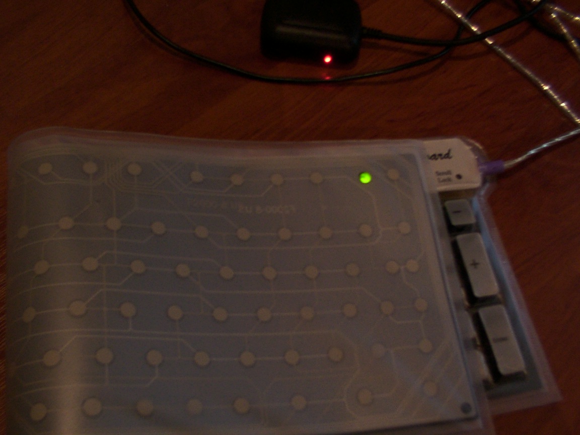
Wooohoo i've found a keyboard (here its not that easy) that kinda fits my needs in an OK price...its made outta gel/nylon very nice, i'm updating the software.
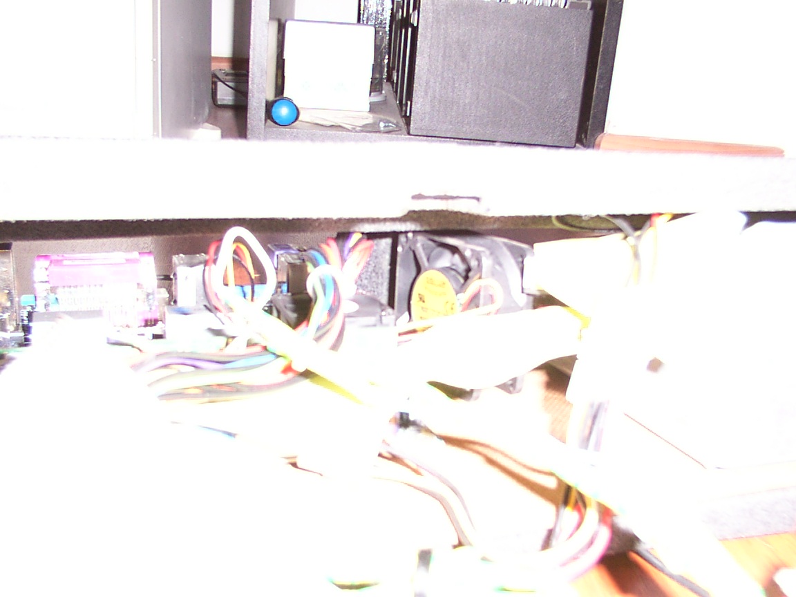
Here you can see the fan at work, i havent mounted it , because i dont think he'll ever move due to its height and the available height of the glovebox(the height there changes, its not constant all the way).
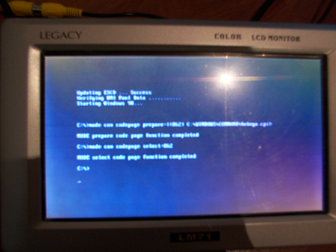
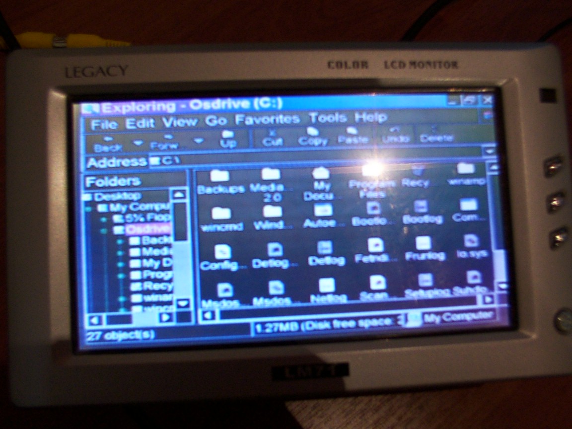
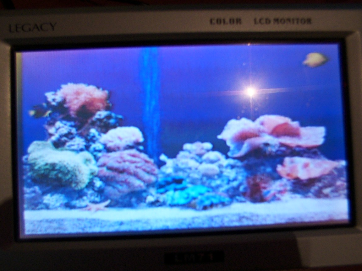
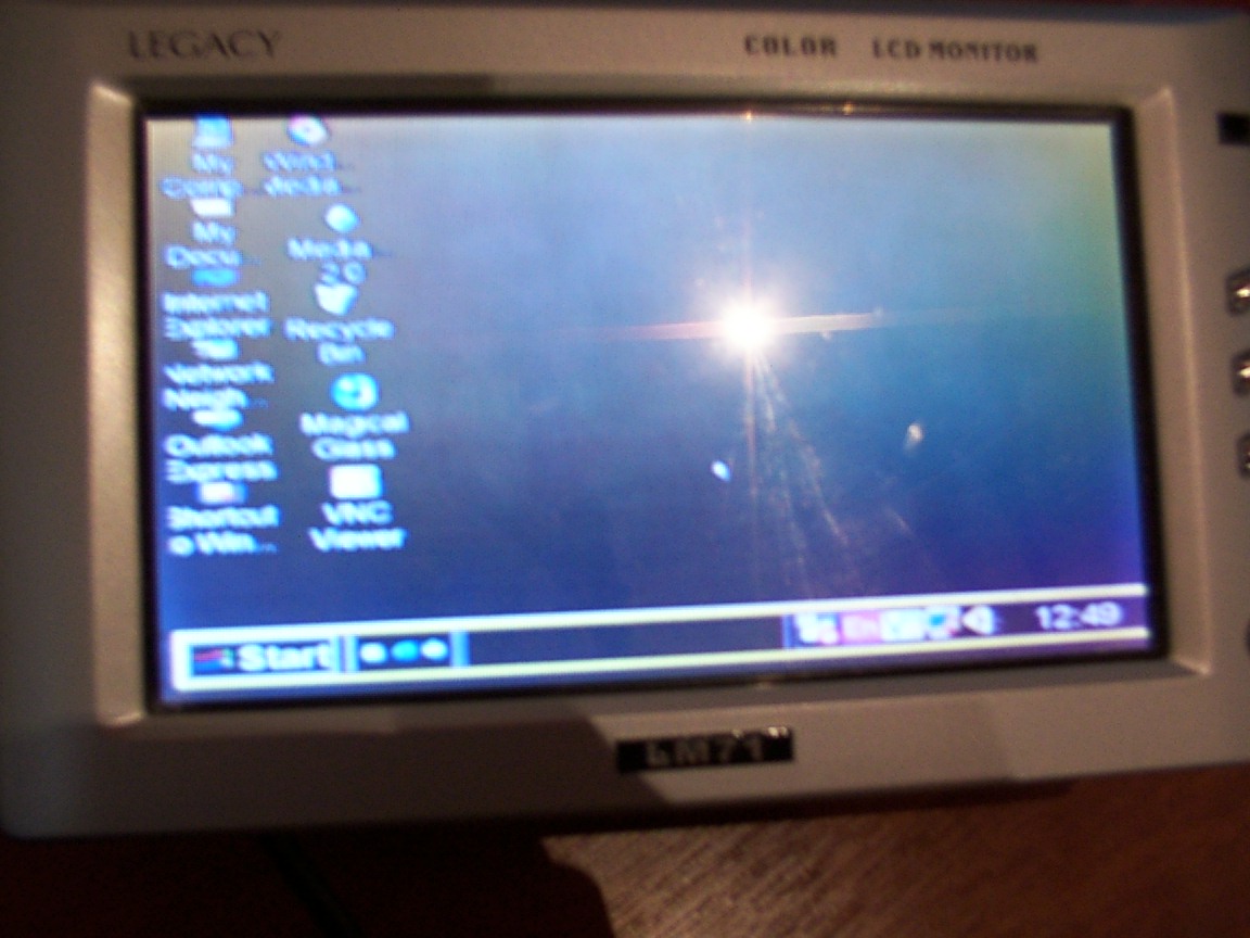
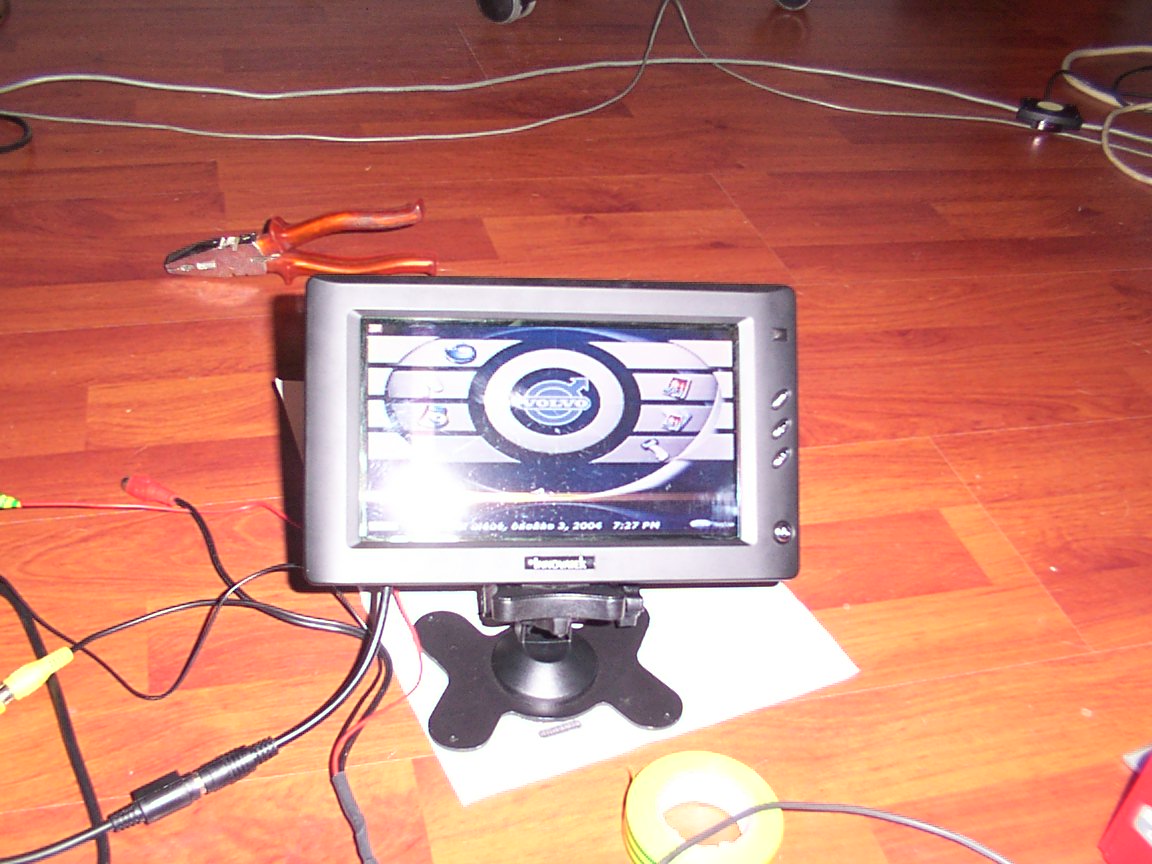
Tried taking a good picture of the monitor, not that easy taking a picture of a monitor, especially a STN one.
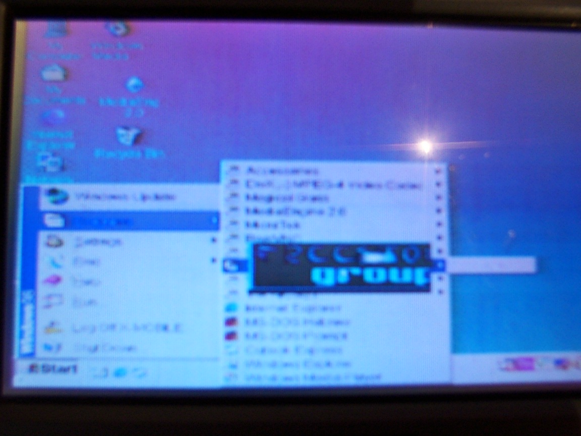
Here is ME at work, with my custom logo, was hard pasting that logo in there :) i hate GFX
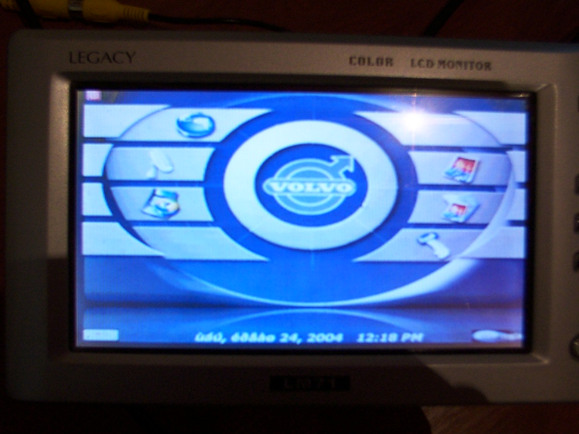
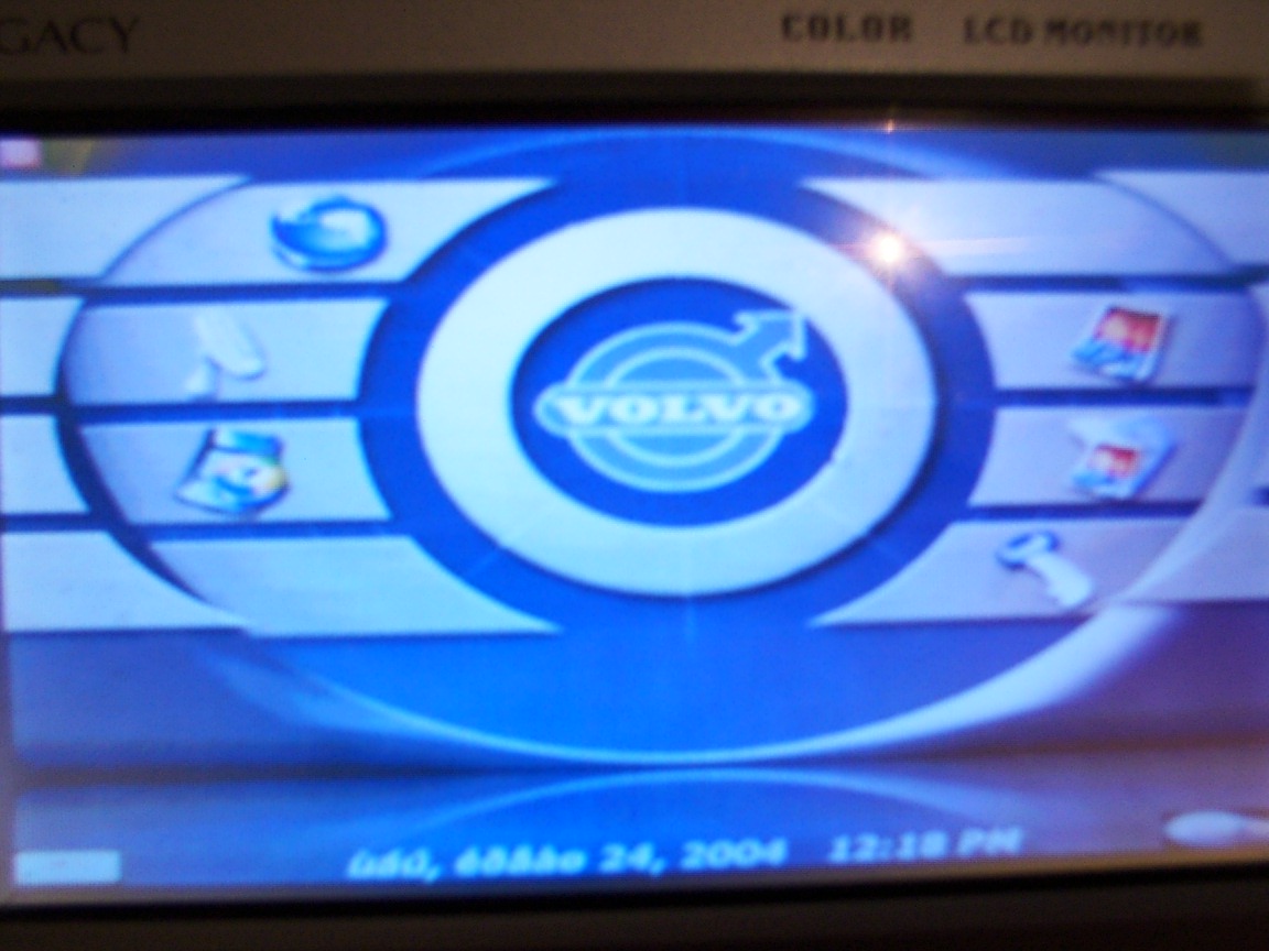
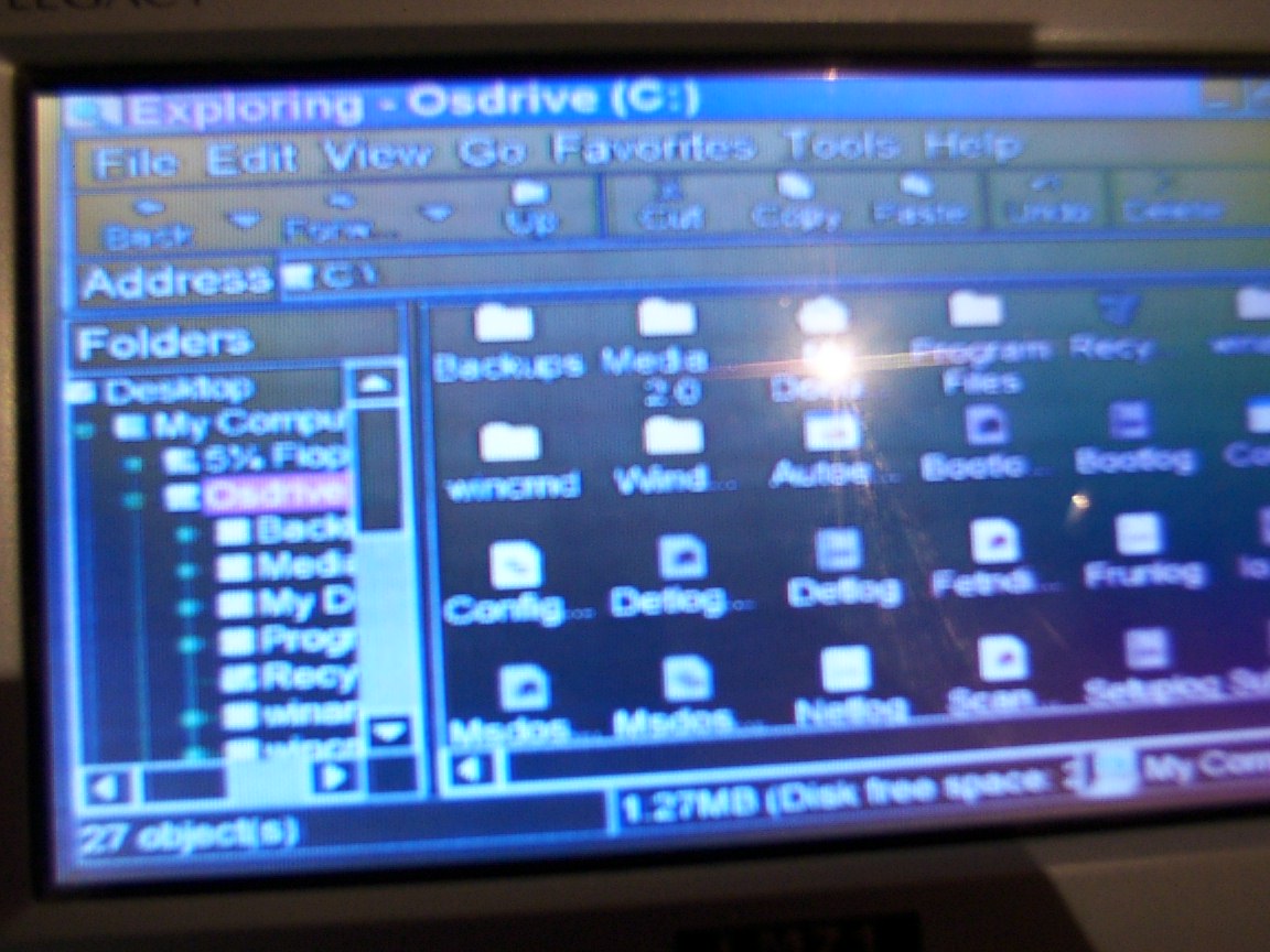
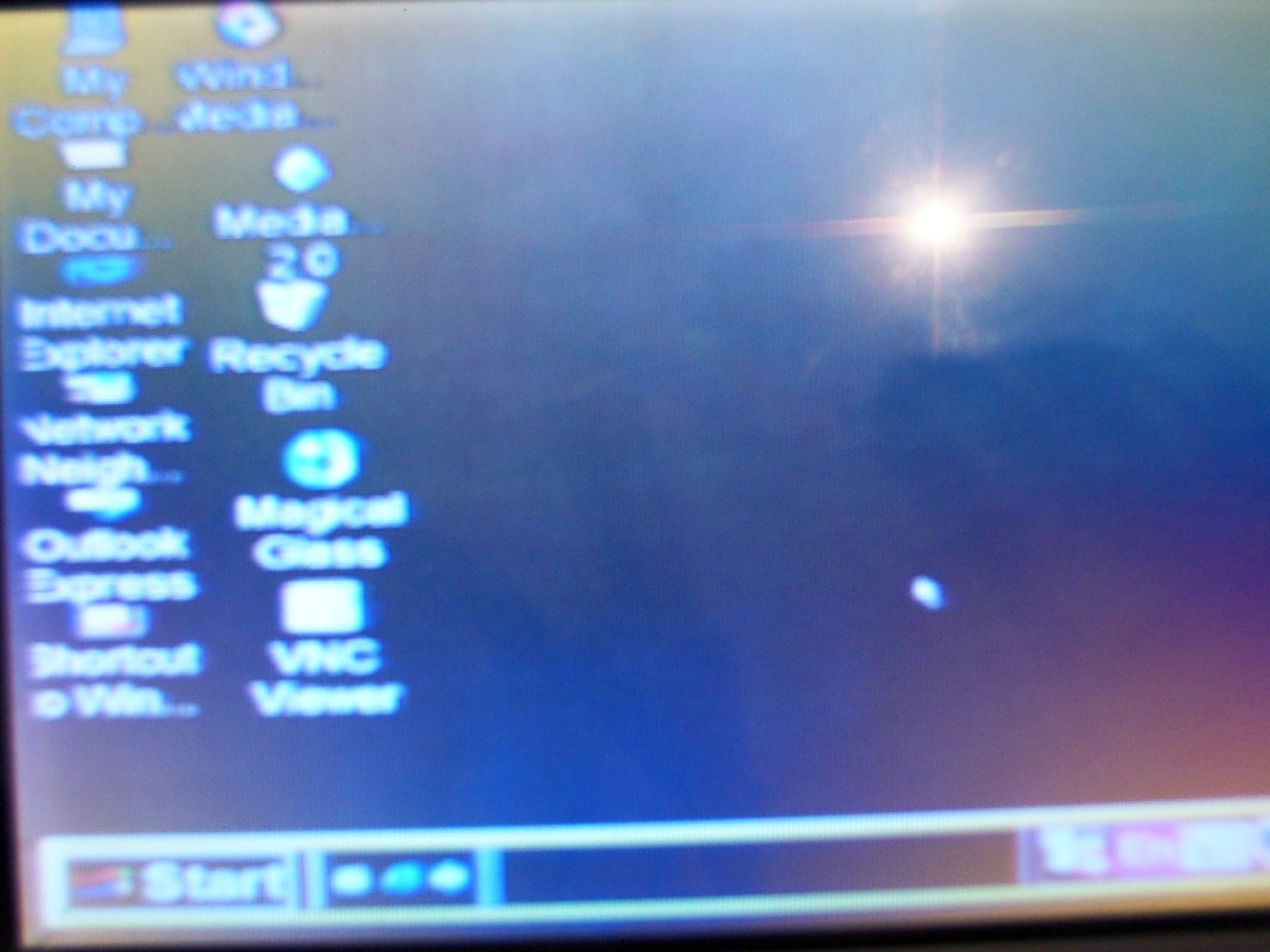
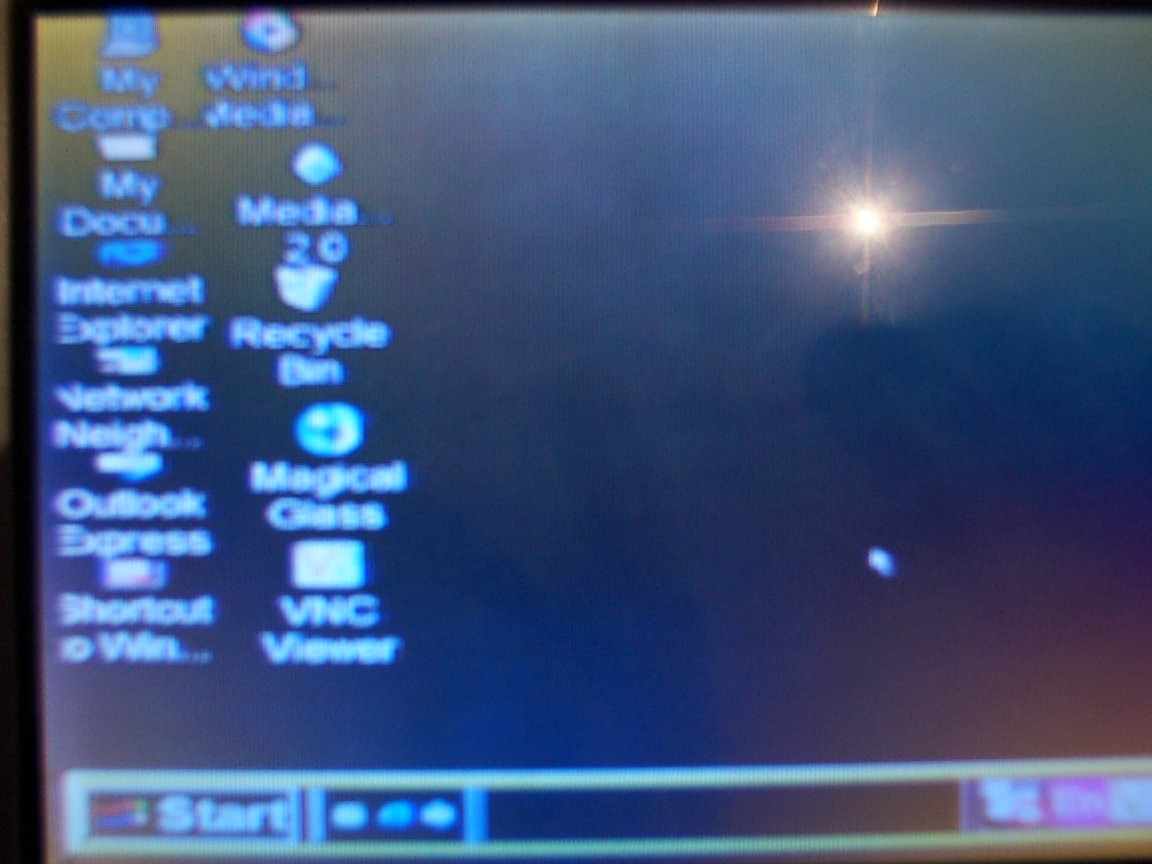
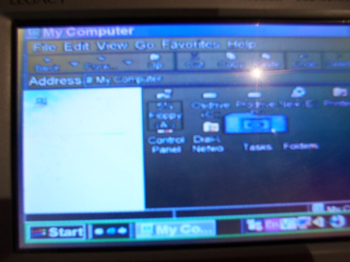
Using Explorer, the windows appearance is on high resolution extra large... well what've you expected?
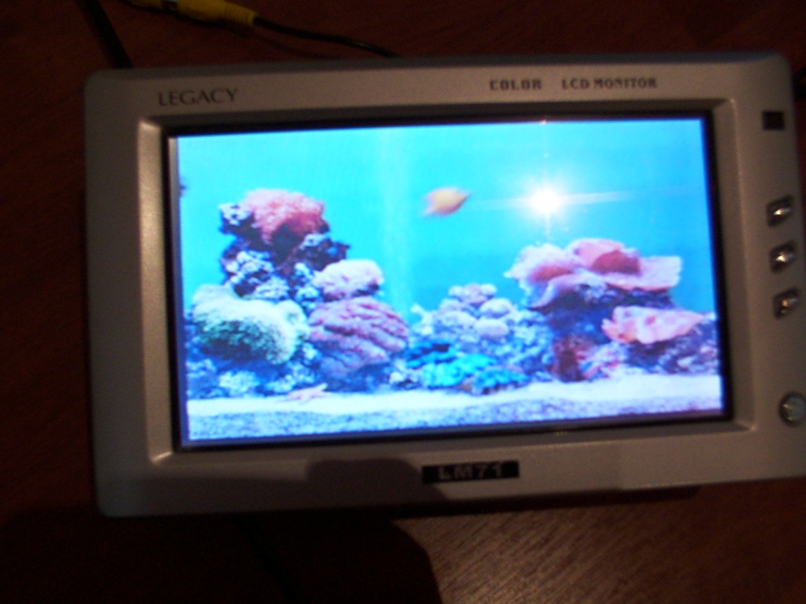
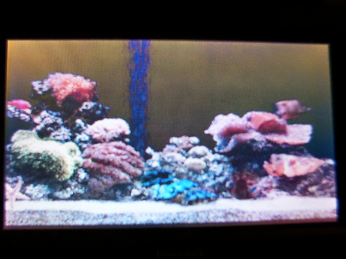
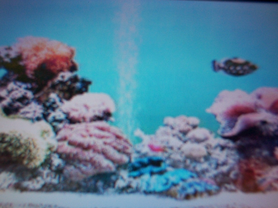
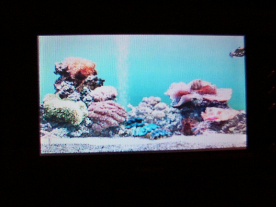
I was in the mood for a screen saver, i just love sachs fish aquarium....
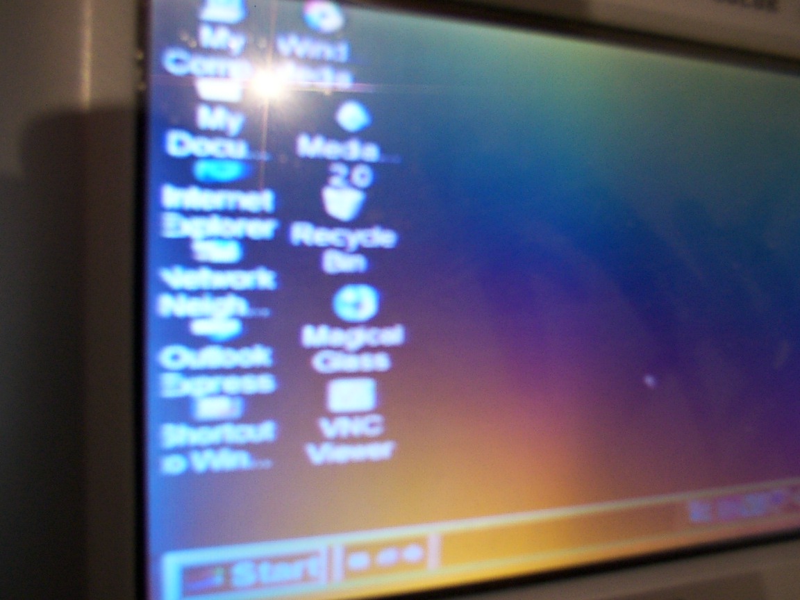
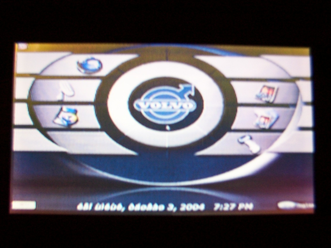
Picture of the monitor from a 40 deg angle as you can see STN and a not straight look doesnt work that well.
Actually for driving i guess its good, if you can see what you want to do , dont do it right now, break at the side and watch it then.
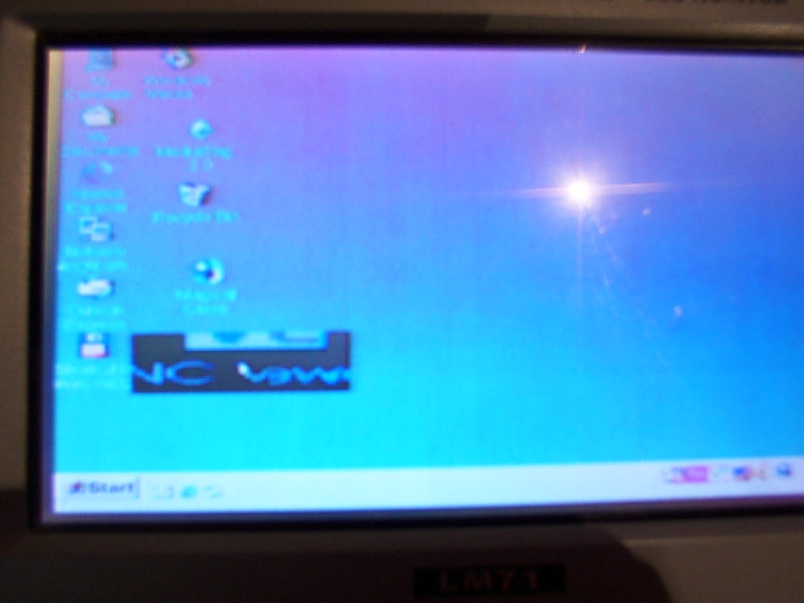
You see the big NC in the black rectangle there? its the magic glass program, what a program i tell you.
It uses overlay for magnifying the area underneath it , got options like zoom in/out , enlarge magnifying area, different magnifying glasses , auto starting and more.I recommend it.
This is the usb gps that got a lock and the gel keyboard from behind, pretty cool ha :) i like the touch of the gel / nylon keyboard its very nice though it got the size of a regular keyboard that a shame...
Here i've soldered the screen electricity cable to the DC output plug , the yellow wire soldered to the red(positive) the yellow wire from the dc(hdd dc for e.g from the psu) is the 12V, and the black wire just next to it was soldered to the black wire of the monitor (the negative), the black write of the dc plug is the GND.

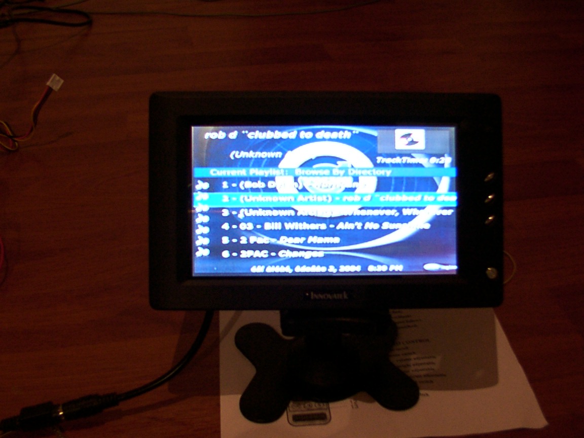
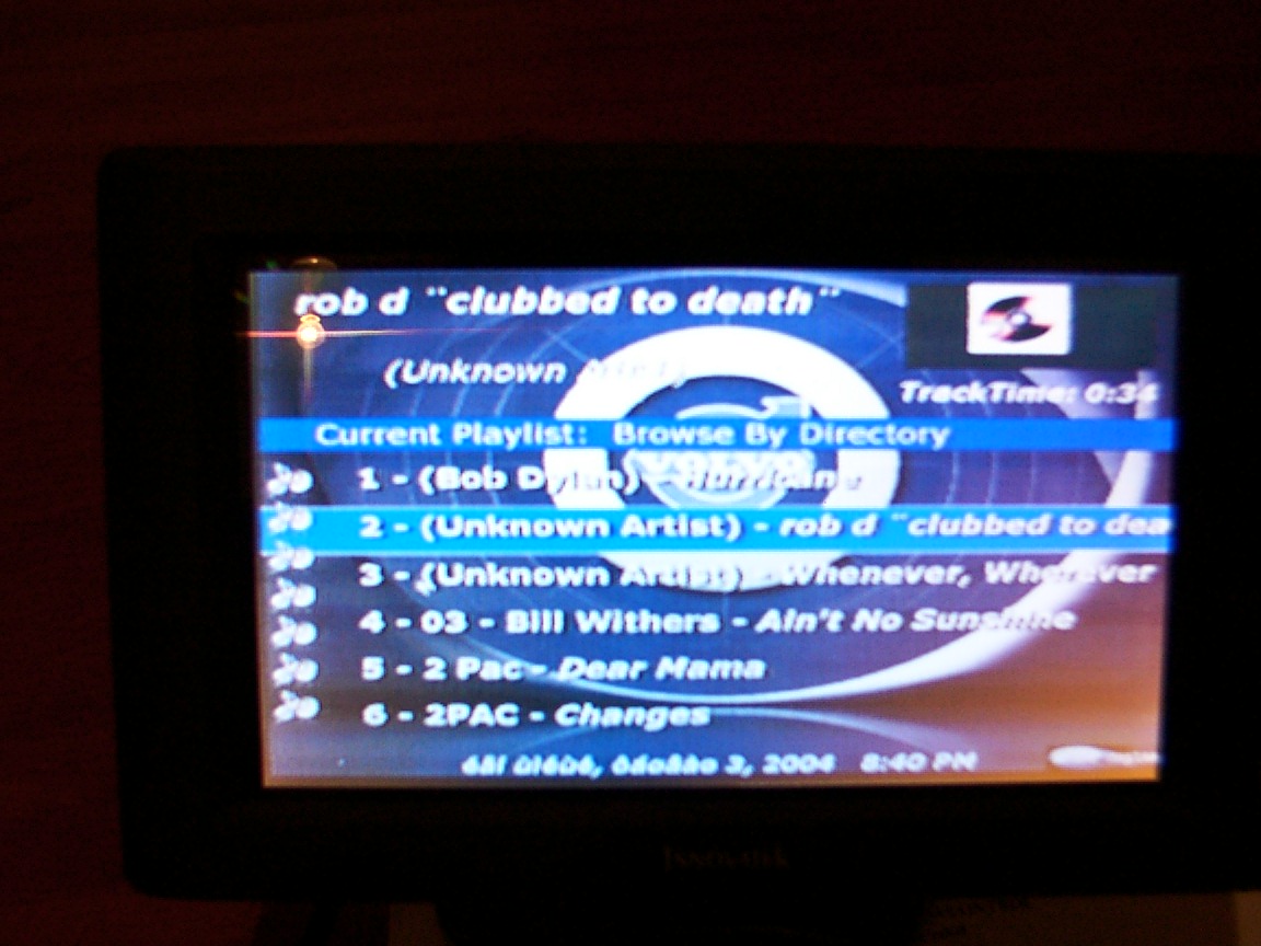
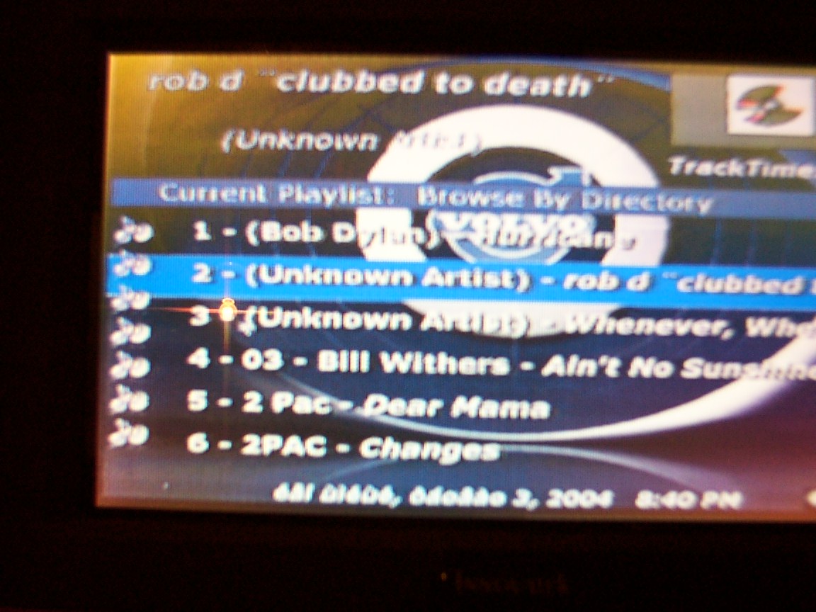
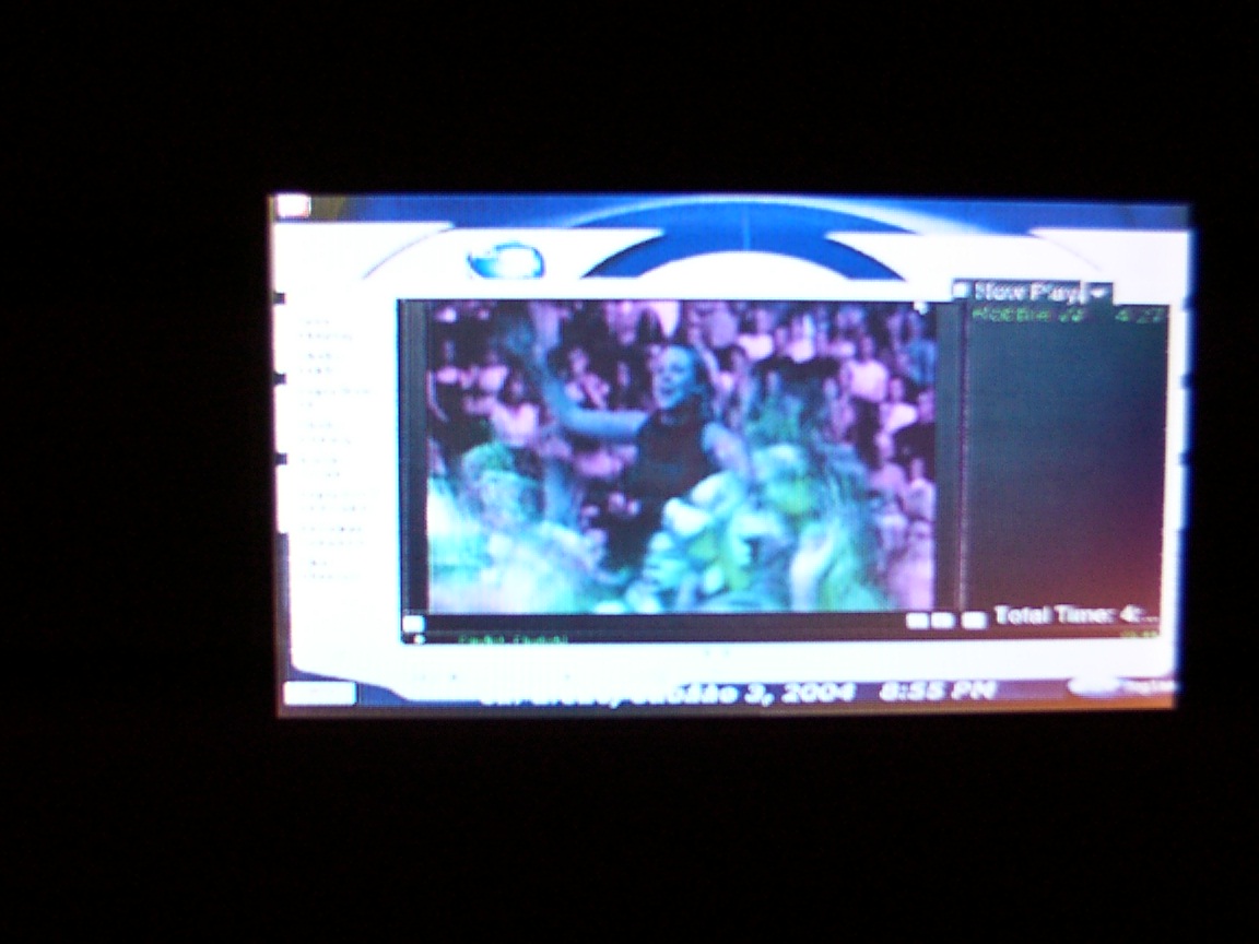
ME playing mp3 - rob d clubbed to death(from "The Matrix" movie) to be honest..

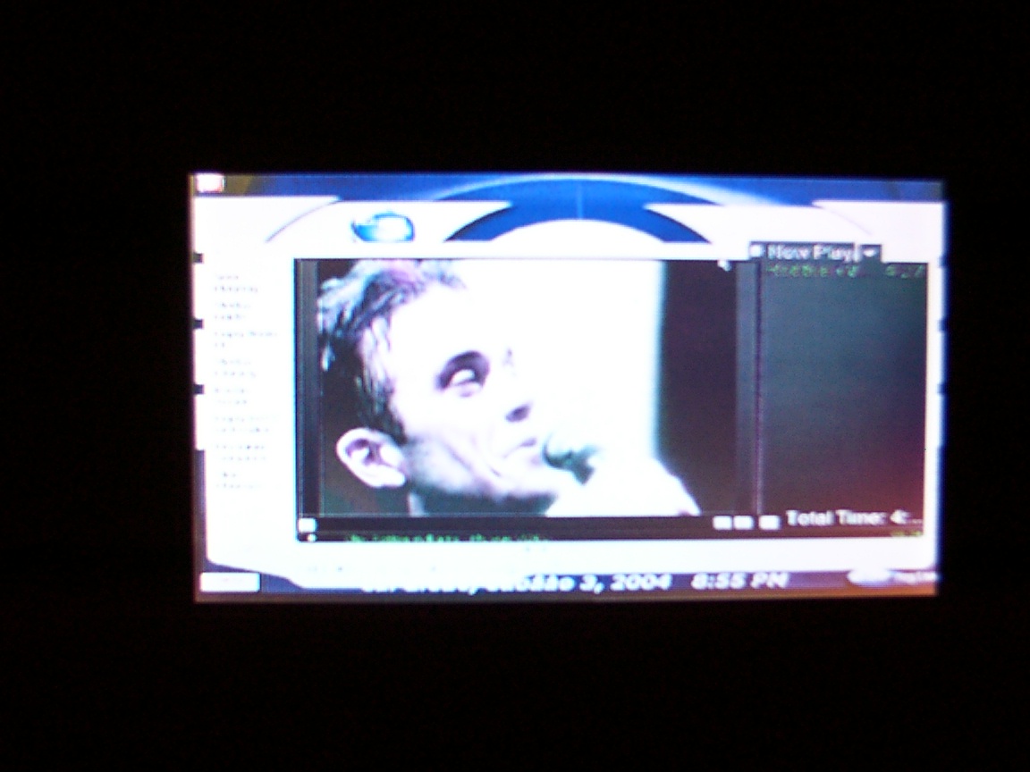
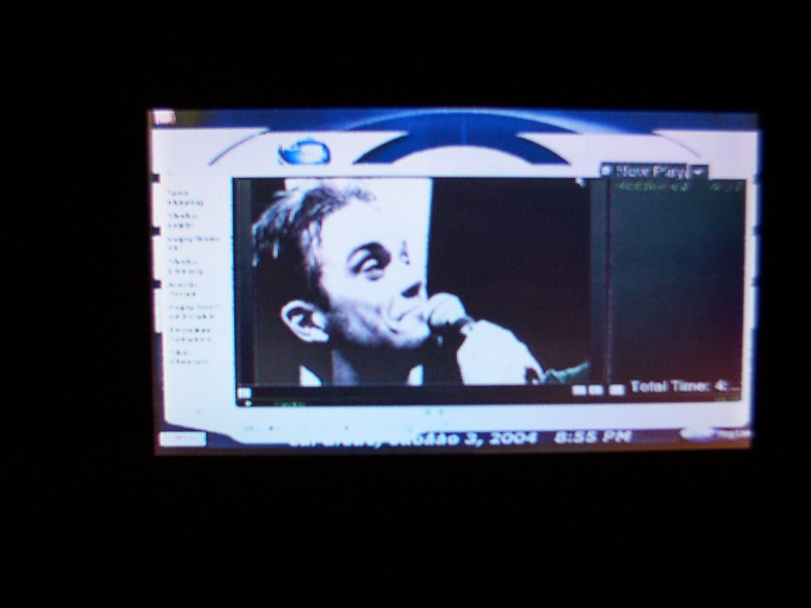
Media player v9 plays robbie willimas singins my way...cant beat that...ho and its at night so you can see how the STN performs at night.
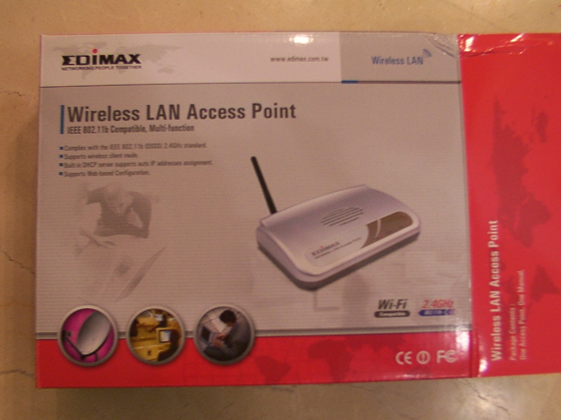
God knows why but i was very happy to get the wireless lan goodies and i decided to take more pics of the STN sachs screen saver...
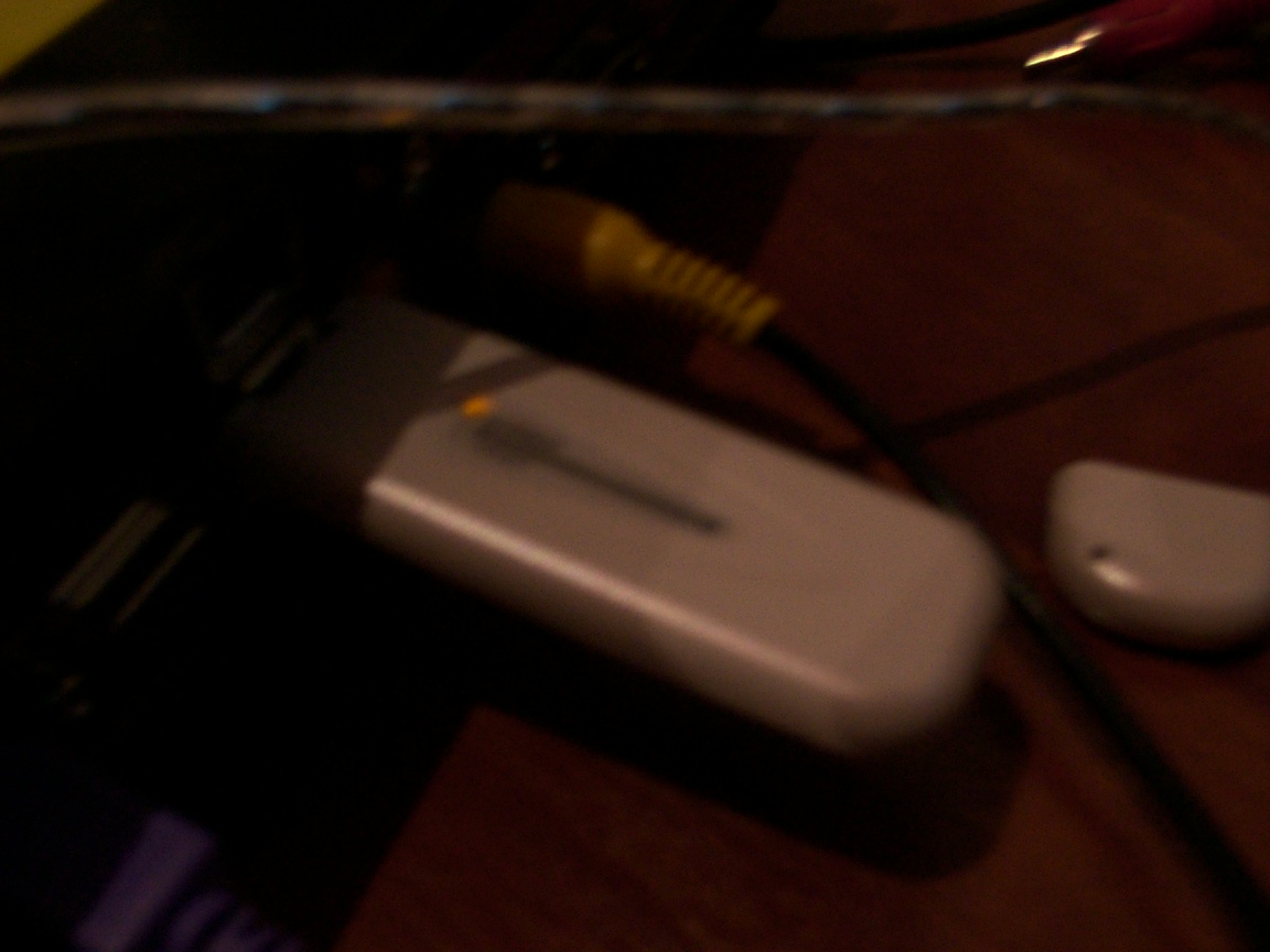
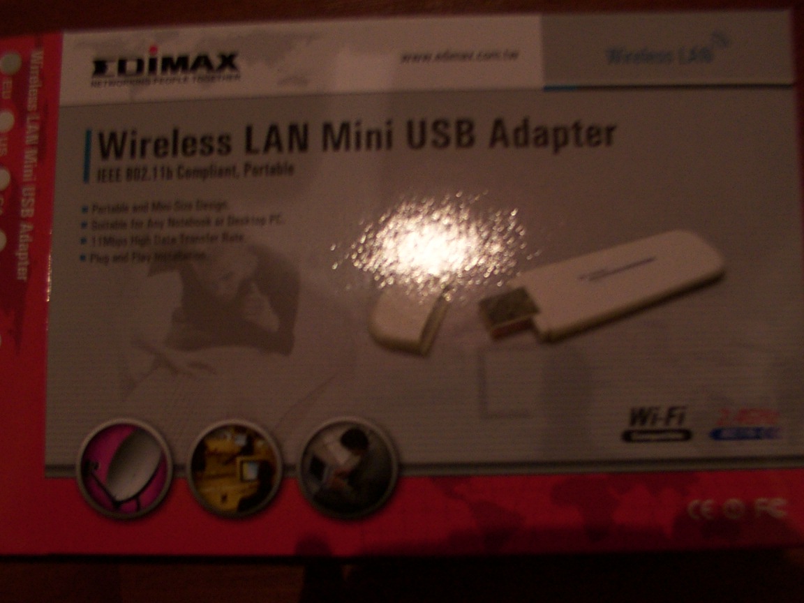
Here we go: I've got the edimax 7117U usb wireless lan adapter 11mbps in the pic and the edimax wireless access point WI-FI 802.11 2.4ghz very cool, and pretty easy to install.it comes with a nice usb 2 cable as shown in the pic.
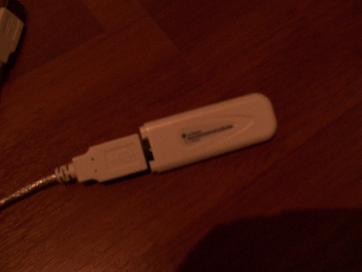
The wireless lan adapter in stuck in the usb port, i've passed tones of files to it today. As you can see the light is on there...
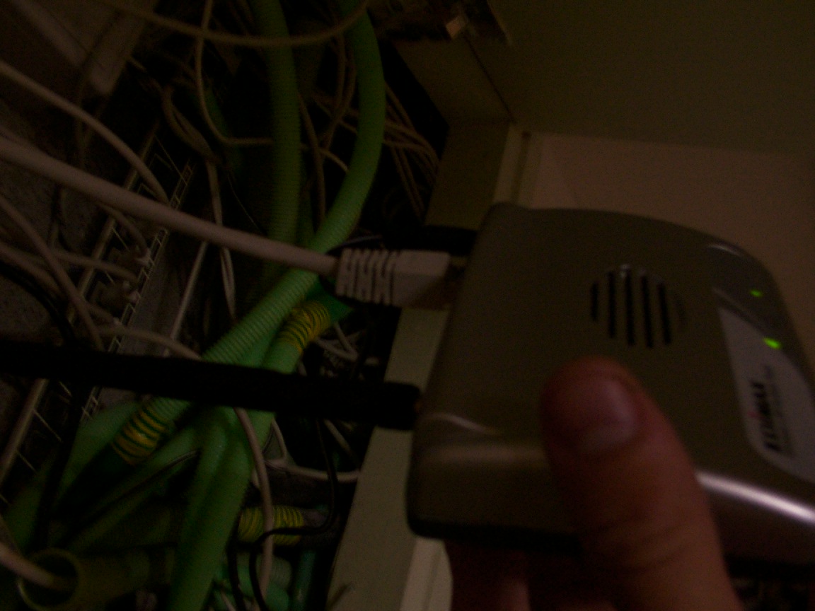
The wireless access point connected to the switch, very cute, i've enjoyed using it. I really did.
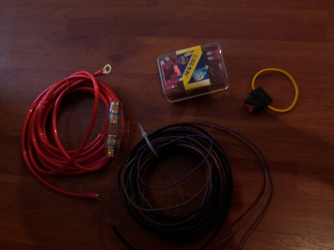
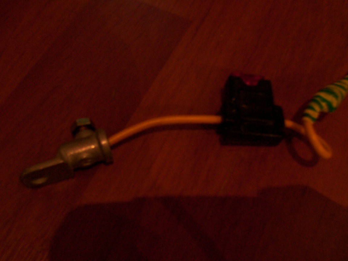
The IGN/POWER/GROUND and another POWER(my backup one...- the red with the big fuse) cables+
the blade 10 amps fuse with a house for it.
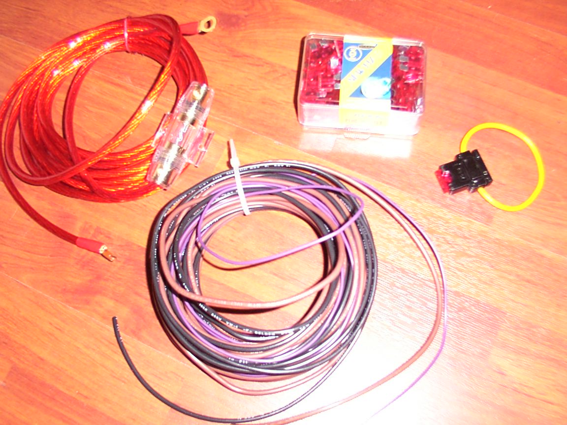
I bought 100 10amps blade fuses..(couldnt find less than that!!! arrr) but its cheap as hell...
The 12v (+) cable soldered to the 10am blade fuse house and got him self a battery cable ring connector like the GND (-) cable.
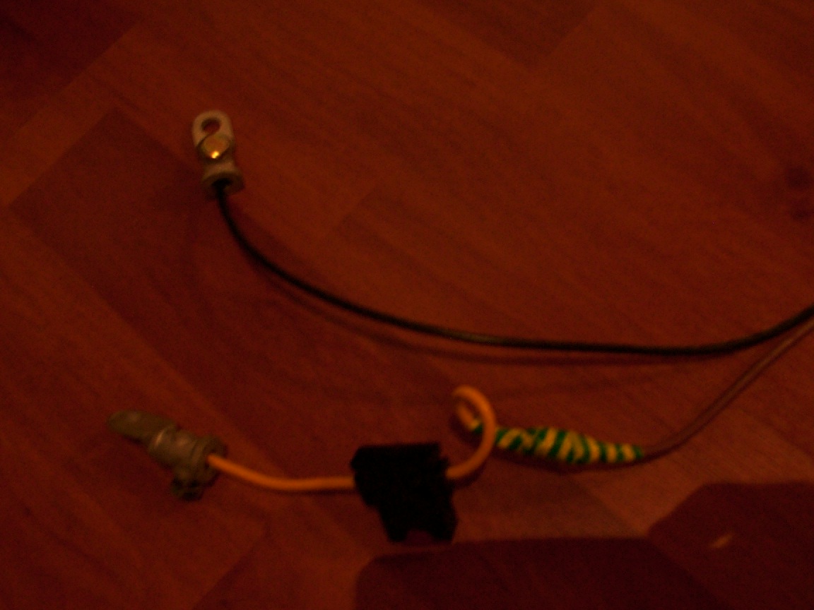
Here you can see em all, the IGN cable soldered to the 12V (+) cable and to the GND (-) cable and in the bottom
will be soldered to the switch.
Here , its very hard seeing it but still, theres the IGN cable soldered to one CAT 5E tendon, and afterwards the continuation of the IGN cable is soldered to the other CAT 5E tendon. The CAT 5E tendons (2 tendons ofcourse) is soldered to a metal button (1 power/0 no power). Thus i will open the carpc whenever i'd want without having to power up the car or having it power up even for a short drive to the store.
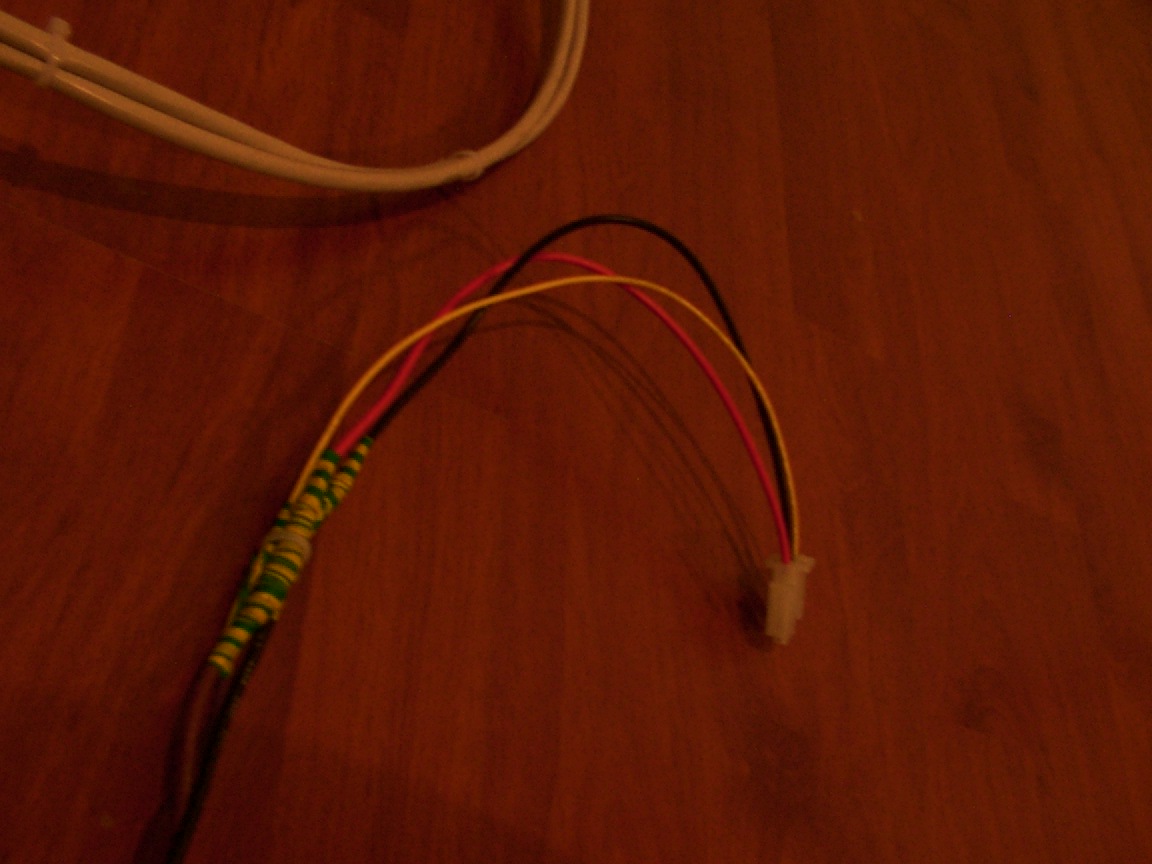
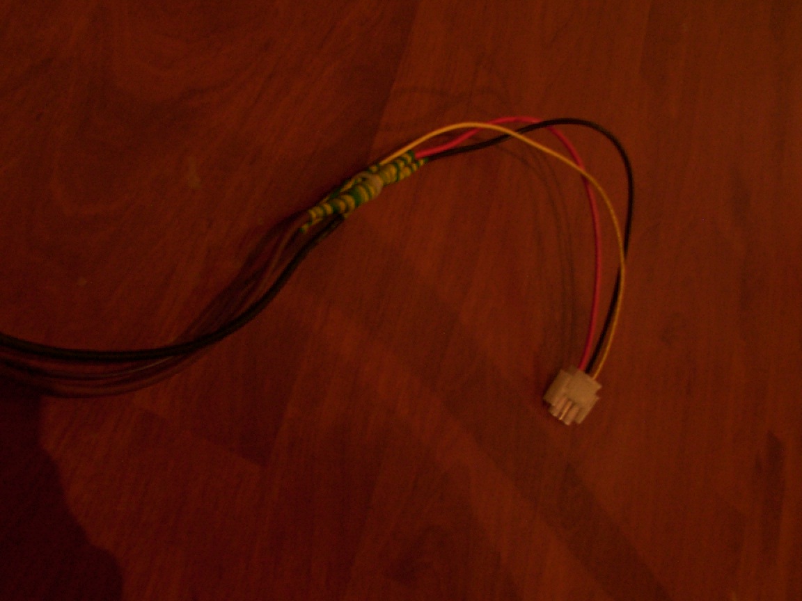
you can see the 12V(red/brown) cable soldered to the red opus cable, the GND (black) cable soldered to the opus black cable and the IGN (grey/maroon) cable soldered to the yellow opus cable.
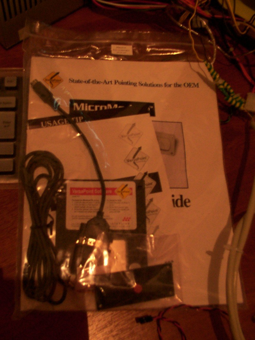
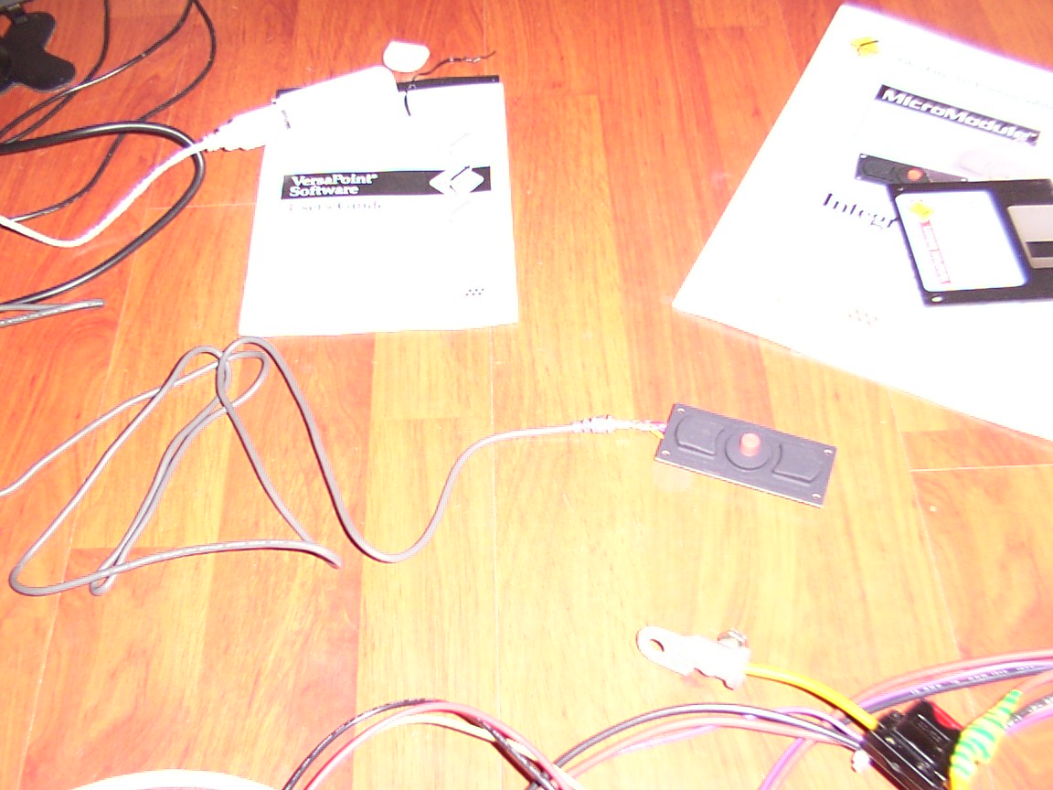
The package the "InterLink MicroModule pointing device" comes in...
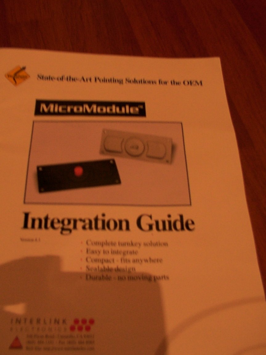
Its guide:
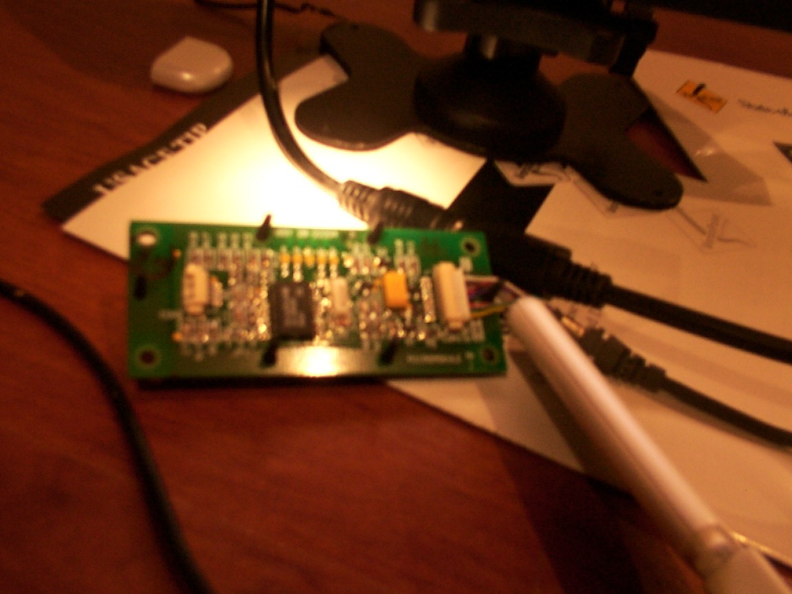
The "MicroModule" in work (with flash):
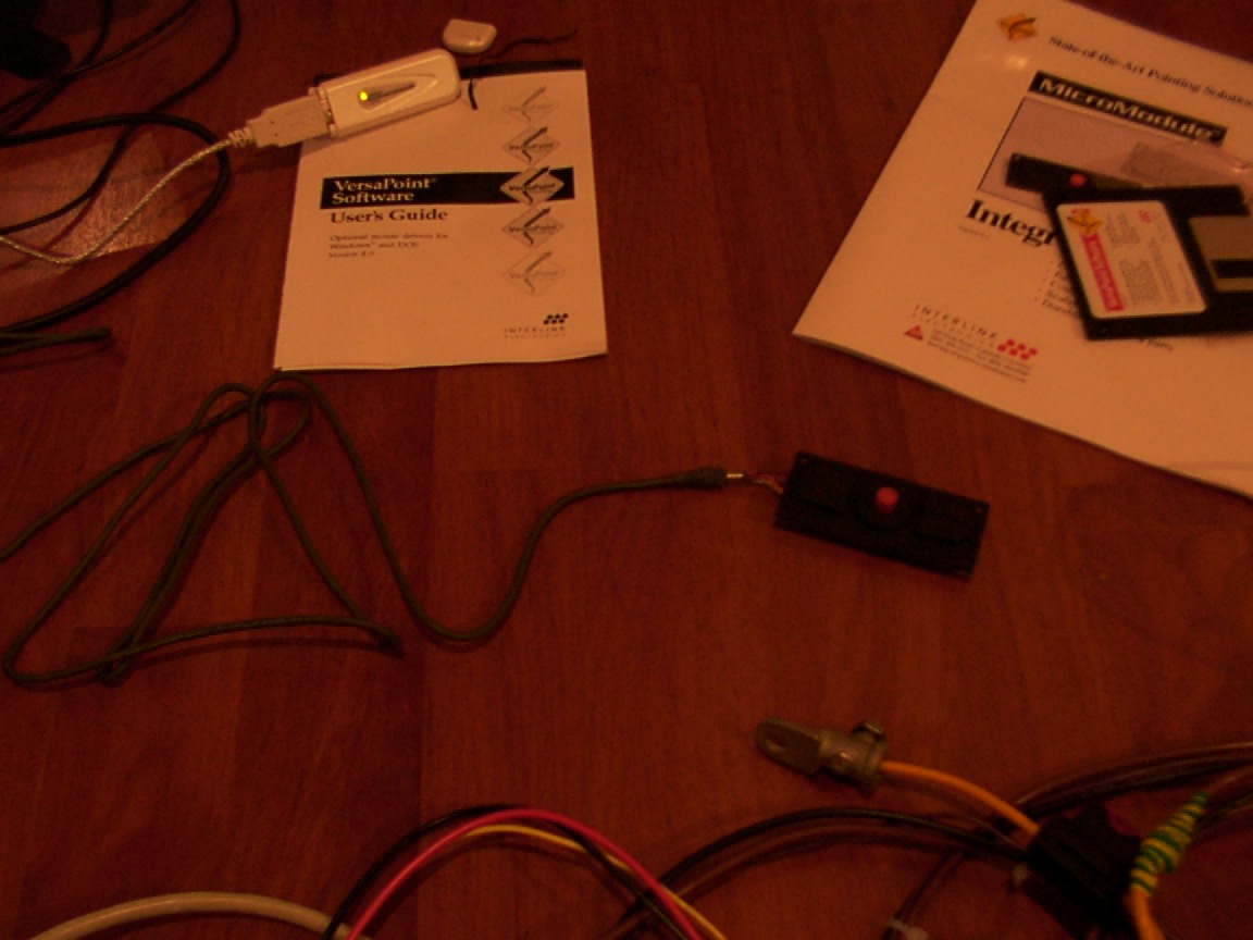
Without flash
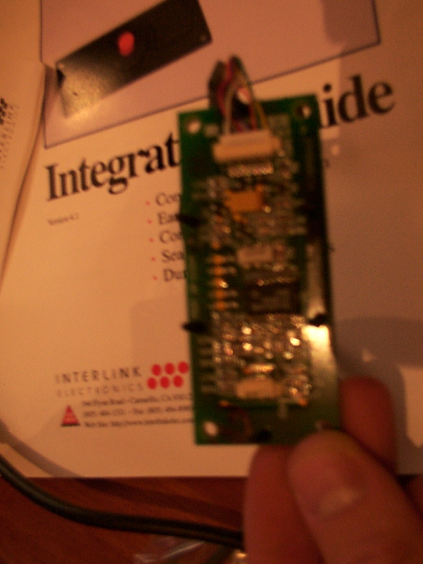
The "MicroModule" PCB (from the back):
Very cool i must say...
Expect more updates to occur soon, also links to informative carpc resources and more...Stay tuned.